hexagon logo

Hi im struggling to understand positional tolerances

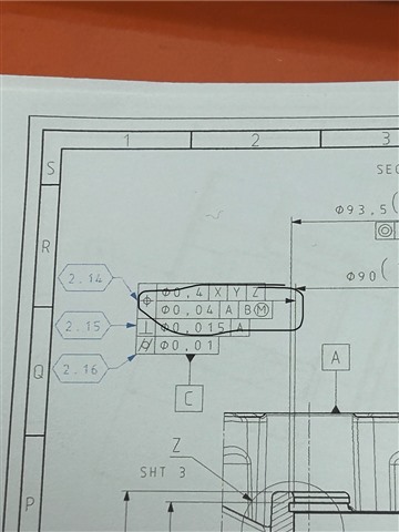
Hello this is going to be a stupid question but im new to CMMing, on my drawing ive been given a positional tolerance of .04mm of a bore with 2 datums, 1 being a different bore and another being the top face of the part, the size of the bore is correct when i measure it with location dimension but when i measure it with the position dimension its saying it is undersize, i dont quite understand where the other numbers are coming from in the box underneath, thank you

  • On your Feature Control Frame, see that word "DEFAULT". It appears your diameter measurement is most likely Least Squared, whereas the FCF is reporting the maximum material condition. Go into the Geometric Tolerancing and in the second tab, change it to Least Squares. Or change the Feature_Math and Datum_Math to Least Squares in the command right on the code.

    I would have your operators increase the size of the bore, as you are 0.004 from being out of spec at LSQ. If that were to be measured as a "fitting condition", it would be out of tolerance. That is what the GD&T is telling you.

  • Thank you that worked

    We aren't making these we just have to measure them for the customer, it is coming up now as the right size but the nominal size is saying the size it is being measured at not the actual nominal size, can you explain why im getting X: -103 and Y:0 in the box below? thank you

  • The size shown in the ACTL field of the feature is based on the math used to calculate it - in most cases this will be Least Squares (unless you've deliberately changed it).  This is also the size that is reported in the location dimension.  Least Squares is an average through the points and, although it is a very stable and repeatable calculation, it will always yield a size that is inside the true surface.  This is one of the reasons why you are often unable to tally CMM measurements with hard gauging methods (the CMM may say the diameter is wrong but a plug gauge fits for example). 

    The size being reported by the geometric tolerance command is the UAME (unrelated actual mating envelope).  This is simulating a true plug gauge fit because, rather than simply report the pre-resolved least squares size from the ACTL field of the feature, it takes all of the measured hits and recalculates using constrained L2 math (constrained L2 is the default math defined by ASME Y14.5 which is why the math setting in the command says DEFAULT).  For an internal diameter, the UAME will be the largest diameter which would fit within the points (simulating a plug gauge).  For an external diameter the UAME would be the smallest diameter which would encompass all the points (simulating a ring gauge).  If you look at the geometric tolerance command, there is a "report local size" setting.  You should really turn this ON to get the full picture because UAME and local size are both required to pass in order for the part to meet specification.  In the case of an internal circle again, if UAME is the smallest diameter (external to material) then the local size would report the biggest, with the range between UAME and local size indicating the amount of form error.  Obviously, how closely the CMM size correlates with an actual hard gauge will be down to the number of points you take when measuring your circles.