hexagon logo

Subtracting radii of two featured circles?

Greetings all. Finally navigated to correct spot in Nexus from PCDMIS forums in hopes to figure this out. . .

Is there a way to subtract the radii of two different size diameters of featured circles that have the same center point, they are parallel, but they are offset.?

Parents
  • I'm not entirely following what you are after, but there is likely a way to do what you are referring to.  

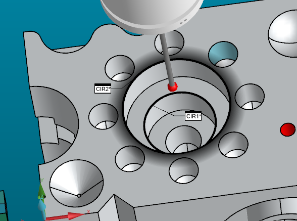
    In the example, I will use these two circles.  

    Create an assignment to do the math to average the diameters.  The code for the assignment is below.  (Assignments are covered in PC-DMIS 300 class.)

    ASSIGN/V1=(CIR1.D+CIR2.D)/2  


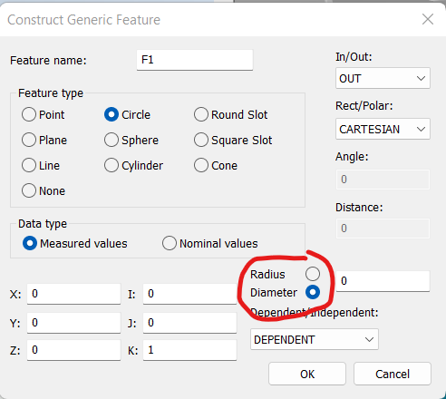
    Construct a generic circle, but be mindful of whether you are doing so with the size in terms of radius or diameter.  Don't bother entering the variable into the dialog.  Do it in the Edit Window instead. 


    In the code below, I edited the measured diameter to use the variable that will be calculated on every execution.  I also entered the nominal diameter, which would be 25 in this case.  

    F1 =GENERIC/CIRCLE,DEPENDENT,CARTESIAN,OUT,$
    NOM/XYZ,<0,0,0>,$
    MEAS/XYZ,<0,0,0>,$
    NOM/IJK,<0,0,1>,$
    MEAS/IJK,<0,0,1>,$
    DIAMETER/25,V1

    I can then report out the radius. 


    DIM 1= LOCATION OF CIRCLE F1 UNITS=MM ,$
    GRAPH=OFF TEXT=OFF MULT=10.00 OUTPUT=BOTH HALF ANGLE=NO
    AX MEAS NOMINAL +TOL -TOL DEV OUTTOL
    R 12.500 12.500 0.025 0.025 0.000 0.000 -#--
    END OF DIMENSION 1

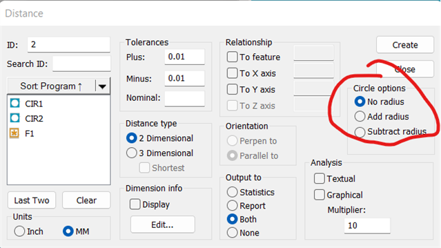
    Initially, I questioned if you were doing it in terms of a distance, but the parallel comment makes me assume that is not correct. If I am incorrect in that assumption, the below may help. 

Reply
  • I'm not entirely following what you are after, but there is likely a way to do what you are referring to.  

    In the example, I will use these two circles.  

    Create an assignment to do the math to average the diameters.  The code for the assignment is below.  (Assignments are covered in PC-DMIS 300 class.)

    ASSIGN/V1=(CIR1.D+CIR2.D)/2  


    Construct a generic circle, but be mindful of whether you are doing so with the size in terms of radius or diameter.  Don't bother entering the variable into the dialog.  Do it in the Edit Window instead. 


    In the code below, I edited the measured diameter to use the variable that will be calculated on every execution.  I also entered the nominal diameter, which would be 25 in this case.  

    F1 =GENERIC/CIRCLE,DEPENDENT,CARTESIAN,OUT,$
    NOM/XYZ,<0,0,0>,$
    MEAS/XYZ,<0,0,0>,$
    NOM/IJK,<0,0,1>,$
    MEAS/IJK,<0,0,1>,$
    DIAMETER/25,V1

    I can then report out the radius. 


    DIM 1= LOCATION OF CIRCLE F1 UNITS=MM ,$
    GRAPH=OFF TEXT=OFF MULT=10.00 OUTPUT=BOTH HALF ANGLE=NO
    AX MEAS NOMINAL +TOL -TOL DEV OUTTOL
    R 12.500 12.500 0.025 0.025 0.000 0.000 -#--
    END OF DIMENSION 1

    Initially, I questioned if you were doing it in terms of a distance, but the parallel comment makes me assume that is not correct. If I am incorrect in that assumption, the below may help. 

Children
  • So, thanks for your reply. The dimension is as above highlighted (.100). Z axis is straight up & y axis is left to right. These surfaces have the same center, just different size diameters.

    CAD above shows the surfaces. 

    What I did was take two circles on these surfaces & I am trying to find the difference of .100 above. My mind is drawing a blank on how to do this other than subtract the two radii manually. Is there an easy way to do this at an angle (feature to feature, can this easily be done in z or y axis's, or can this be done with math? 

    The dimension .070 was easily had as I could take a hit at .000 y axis (center of part) for both the rib and bottom to get a dimension in z axis. However, the .100 is not in any given x,y,z axis, but they are both diameters with the same center point..

    Thanks for your time and help.

  • YOU CAN DO THIS WAY

    PNT8 =FEAT/CONTACT/VECTOR POINT/DEFAULT,POLAR
    THEO/<0.3,280,0>,<0.1736482,-0.9848078,0>
    ACTL/<0.3,280,0>,<0.1736482,-0.9848078,0>
    TARG/<0.3,280,0>,<0.1736482,-0.9848078,0>
    SNAP=NO
    SHOW FEATURE PARAMETERS=NO
    SHOW CONTACT PARAMETERS=YES
    AVOIDANCE MOVE=NO
    SHOW HITS=YES
    HIT/BASIC,<0.3,280,0>,<0.1736482,-0.9848078,0>,<0.3,280,0>
    ENDMEAS/
    PNT9 =FEAT/CONTACT/VECTOR POINT/DEFAULT,POLAR
    THEO/<0.3,290,0>,<0.3420201,-0.9396926,0>
    ACTL/<0.3,290,0>,<0.3420201,-0.9396926,0>
    TARG/<0.3,290,0>,<0.3420201,-0.9396926,0>
    SNAP=NO
    SHOW FEATURE PARAMETERS=NO
    SHOW CONTACT PARAMETERS=YES
    AVOIDANCE MOVE=NO
    SHOW HITS=YES
    HIT/BASIC,<0.3,290,0>,<0.3420201,-0.9396926,0>,<0.3,290,0>
    ENDMEAS/
    PNT10 =FEAT/CONTACT/VECTOR POINT/DEFAULT,POLAR
    THEO/<0.3,300,0>,<0.5,-0.8660254,0>
    ACTL/<0.3,300,0>,<0.5,-0.8660254,0>
    TARG/<0.3,300,0>,<0.5,-0.8660254,0>
    SNAP=NO
    SHOW FEATURE PARAMETERS=NO
    SHOW CONTACT PARAMETERS=YES
    AVOIDANCE MOVE=NO
    SHOW HITS=YES
    HIT/BASIC,<0.3,300,0>,<0.5,-0.8660254,0>,<0.3,300,0>
    ENDMEAS/
    ASSIGN/AVG1=(PNT8.PR.M+PNT9.PR.M+PNT10.PR.M)/3
    F4 =GENERIC/POINT,DEPENDENT,CARTESIAN,$
    NOM/XYZ,<73.43172,-24.32854,83.06375>,$
    MEAS/XYZ,<AVG1,-24.32854,83.06375>,$
    NOM/IJK,<0.0022082,0.0129749,0.9999134>,$
    MEAS/IJK,<0.00221,0.01297,0.9999134>
    PNT11 =FEAT/CONTACT/VECTOR POINT/DEFAULT,POLAR
    THEO/<0.4,280,0>,<-0.1736482,0.9848078,0>
    ACTL/<0.4,280,0>,<-0.1736482,0.9848078,0>
    TARG/<0.4,280,0>,<-0.1736482,0.9848078,0>
    SNAP=NO
    SHOW FEATURE PARAMETERS=NO
    SHOW CONTACT PARAMETERS=YES
    AVOIDANCE MOVE=NO
    SHOW HITS=YES
    HIT/BASIC,<0.4,280,0>,<-0.1736482,0.9848078,0>,<0.4,280,0>
    ENDMEAS/
    PNT12 =FEAT/CONTACT/VECTOR POINT/DEFAULT,POLAR
    THEO/<0.4,290,0>,<-0.3420201,0.9396926,0>
    ACTL/<0.4,290,0>,<-0.3420201,0.9396926,0>
    TARG/<0.4,290,0>,<-0.3420201,0.9396926,0>
    SNAP=NO
    SHOW FEATURE PARAMETERS=NO
    SHOW CONTACT PARAMETERS=YES
    AVOIDANCE MOVE=NO
    SHOW HITS=YES
    HIT/BASIC,<0.4,290,0>,<-0.3420201,0.9396926,0>,<0.4,290,0>
    ENDMEAS/
    PNT13 =FEAT/CONTACT/VECTOR POINT/DEFAULT,POLAR
    THEO/<0.4,300,0>,<-0.5,0.8660254,0>
    ACTL/<0.4,300,0>,<-0.5,0.8660254,0>
    TARG/<0.4,300,0>,<-0.5,0.8660254,0>
    SNAP=NO
    SHOW FEATURE PARAMETERS=NO
    SHOW CONTACT PARAMETERS=YES
    AVOIDANCE MOVE=NO
    SHOW HITS=YES
    HIT/BASIC,<0.4,300,0>,<-0.5,0.8660254,0>,<0.4,300,0>
    ENDMEAS/
    ASSIGN/AVG2=(PNT11.PR.M+PNT12.PR.M+PNT13.PR.M)/3
    F3 =GENERIC/POINT,DEPENDENT,CARTESIAN,$
    NOM/XYZ,<73.43172,-24.32854,83.06375>,$
    MEAS/XYZ,<AVG2,-24.32854,83.06375>,$
    NOM/IJK,<0.0022082,0.0129749,0.9999134>,$
    MEAS/IJK,<0.00221,0.01297,0.9999134>
    DIM DIST2= 2D DISTANCE FROM POINT F4 TO POINT F3 (CENTER TO CENTER),NO_RADIUS UNITS=IN,$
    GRAPH=OFF TEXT=OFF MULT=1.00 OUTPUT=BOTH
    AX NOMINAL +TOL -TOL MEAS DEV OUTTOL
    M 0.10000 0.00100 0.00100 0.10000 0.00000 0.00000 ----#----

  • Is it easier to create a constructed pierce point through the two circles?  Of course, creating the line might need to be well thought out.  

    If you are unfamiliar with pierce points, beware the line vector, or you will get a point floating on the wrong side of the circle.  

  • If you do your way, you will only have a measurement in one place. Remember this is a small Arch and you have to be very careful. That's why I use several polar points and take the average from them. A more accurate measurement in my opinion.