hexagon logo

Dimensioning Datums for MMB

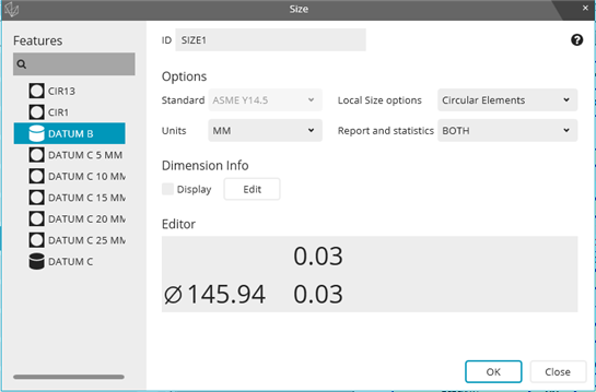
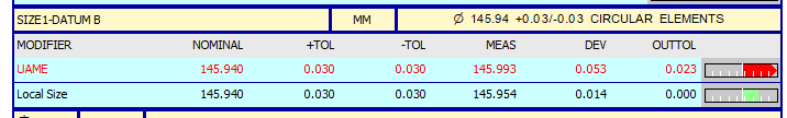
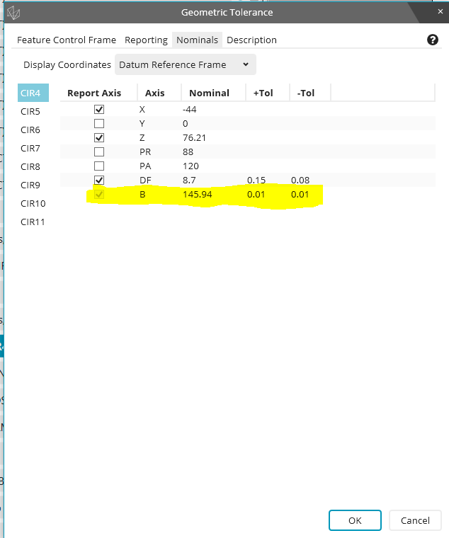
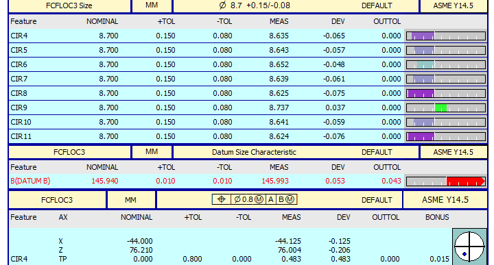
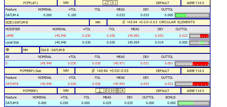
As I understand it, if you want to apply a MMB modifier to a datum in a FCF, you must first ensure that said datum has already been dimensioned with tolerances to determine its MMC and LMC.  So my question is, does it need to be dimensioned with a size dimension and default math, or will a location dimension with LSQ math also work?  And if you happen to have both in your routine (with the same tolerances applied), will that mess up the position calculation?

Parents
  • This is explained in the help file : PC-DMIS Help Center - 2023.2 (hexagonmi.com)

    The easiest thing to do is to include the size in your Geometric tolerance commands for the datums.  If you need to do the sizes separately then you should use a size command, the geometric tolerance command does not recognise location dimensions.

  • Sorry to be a pain in the butt here, but I did a size dimension for one of my datums early on in my routine, then used that datum in a position FCF with a MMB modifier later on in the routine.  When I go to the nominals tab, it's not using the tolerance that I specified earlier in the size dimension.  Do I have to re-enter it?  I thought PCDMIS looked up in the routine to get the tolerance values if available.


  • You need a position or perpendicularity of your datum B cylinder at MMC to datum A.  That position/perpendicularity would include the size.  If you had already added a SIZE command for the datum B cylinder, prior to the position/perpendicularity, then PC-DMIS would read up, see it and auto-populate the size when you are creating that position/perpendicularity of B at MMC to A.  If you have only added a SIZE for datum B and have not added it's position/perpendicularity, then it will not be recognised when you later try to reference it at MMB.

  • I did have a perpendicularity dimension for Datum B.  The tolerance later on still shows up as +\- .01, not .03.  So I'm not sure what I'm doing wrong.  But if I manually change it to .03 in the nominals tab for the FCFLOC3 dimension, will it still calculate the datum shift correctly even if I missed something earlier?  If it makes any difference, this is a routine I created in 2017R1 with XACT Measure and now I'm using 2023.2.

  • Yes, as long as you've ensured all of the tolerances are correct in all of the commands, the datum shift will be applied correctly. 

    I'm wondering why it didn't pick up the previous commands?  If I create a new routine and add the commands in the correct order, everything trickles through correctly so maybe it's a problem with old XactMeasure routines that have been migrated?  Do you still have a copy of the original routine (2017 format) that you could send me so I can ask my team to investigate?

  • Yes I do, though I still wouldn't discount the possibility that I did something incorrectly.  This was a routine that I wrote fresh out of 101 class, so there's probably a lot of questionable and/or embarrassing things in it.  I'm aware that I broke all the naming rules, so maybe that has something to do with it?  My predecessors did the same thing so I didn't know any better at the time.  Anyway, I'm just trying to put some lipstick and mascara on this routine so we have something to use until I can rewrite it.  How should I go about sending you the routine?  Thanks for the help Neil.  Much appreciated as always.  

  • You can use this link to upload your routine (ideally both the .prg and .cad): https://sendit.hexagon.com/filedrop/~TlEOHL

  •  I took a look at the routine you sent me and think I can explain.  The problem is that you're editing existing commands so the tolerances don't automatically ripple through the rest of the program when you change them.  If you were creating a fresh routine, each command would read up and grab the information as they are being created.  To get that same behaviour in existing commands, you need to force them to update by removing and then re-adding the feature.  You would need to do this in the edit window, not the dialog, because the dialog "remembers" what tolerances were previously set.  To do it through the dialog, you would have to edit (F9), remove the feature and replace with something else, then create, then edit (F9) again, restore your original feature and create.

    I also noticed a lot of spaces in your feature and dimension names which can also cause problems, especially when (as you have) there are several names that all begin with the same string (DATUM C ...... in your case).  When you have this type of scenario, PC-DMIS can get in a state where it only reads up to the first space and then doesn't know which item it is supposed to be referencing because, as far as PC-DMIS is concerned, it sees multiple items with the same name.

  • Thank you Neil.  I think that makes sense how I would need to recreate the commands instead of editing existing ones.  I'm definitely going to rewrite this routine later.  Again, it was one of the first routines I wrote out of class, and I wasn't necessarily aware of the problems that improper naming can cause, since my predecessors all did the same thing.  I appreciate you looking at it and all the help you've been.

Reply
  • Thank you Neil.  I think that makes sense how I would need to recreate the commands instead of editing existing ones.  I'm definitely going to rewrite this routine later.  Again, it was one of the first routines I wrote out of class, and I wasn't necessarily aware of the problems that improper naming can cause, since my predecessors all did the same thing.  I appreciate you looking at it and all the help you've been.

Children
  • No problem.  If you do get around to re-writing it, I'd recommend reporting the size of the features as part of the geometric tolerance commands rather than doing them separately.  Your current routine uses location commands for the size and then geometric tolerance commands (with the size turned off) for the GD&T - it's much easier and less prone to error if you do everything in one command.