hexagon logo

Why is the result of a linear closed scan the a line profile related to basis not zero (offline programing)?

Hi,

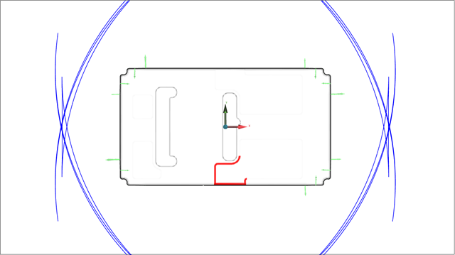
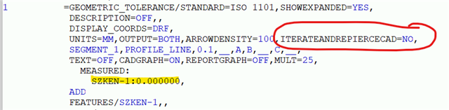
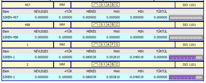
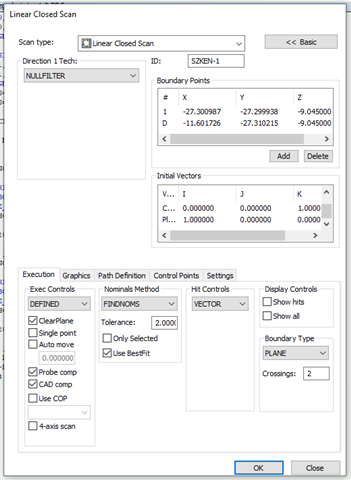
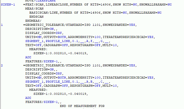
In the case of the offline programing, why is the result of a linear closed scan the line profile related to basis not zero (see dimension 1 and 2)?

the current values of the bases and all elements are currently at nominal.


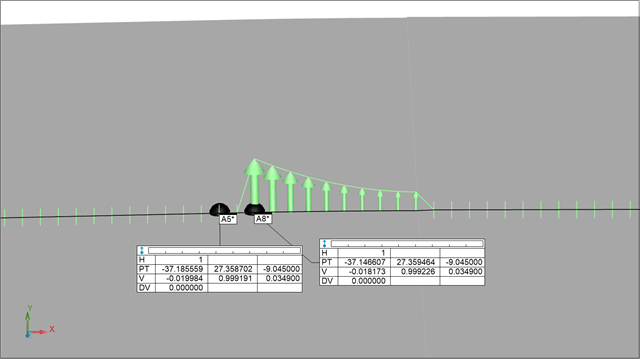
the first two cases show that there is no such problem (dimensions 457 and 458).

Parents
  • Can you send me your .prg and .CAD os I can take a look?  You can use this link to upload them: https://sendit.hexagon.com/filedrop/~TlEOHL 

  • It looks like there are a number of very small surfaces in the CAD model that are causing a problem for some reason.  I increased the magnification and turned on CAD graphics...

    You can see several spikes in the data.  Zooming in and selecting the CAD, you can see that these spikes coincide with the small surface sections (highlighted light blue)...

    Zooming in further and creating two vector points, you can see a difference in the Y co-ordinates...

    This is the deviation being picked up by the Geometric Tolerance command.  It is finding these small surfaces because ITERATEADNREPIERCE=YES is enabled (by default) whenever you do profile or a line or profile of a surface with a CAD model present.  The scan's findnoms appears to be detecting these small surfaces as you can see from the hits for that area (SHOW HITS=YES)...

    But I do not know why there is a discrepancy between the scan's FINDNOMS and the Geometric Tolerance Command's ITERATEANDREPIERCE, I will have to ask my team to investigate.

    In the meantime, if you set ITERATEANDREPIERCE=NO in the Geometric Tolerance command, it will use the nominals found by the scan and you will see zero deviation offline.  It may be worth asking whoever created the CAD model if they know the reason for the small surfaces and if they were added intentionally.

Reply
  • It looks like there are a number of very small surfaces in the CAD model that are causing a problem for some reason.  I increased the magnification and turned on CAD graphics...

    You can see several spikes in the data.  Zooming in and selecting the CAD, you can see that these spikes coincide with the small surface sections (highlighted light blue)...

    Zooming in further and creating two vector points, you can see a difference in the Y co-ordinates...

    This is the deviation being picked up by the Geometric Tolerance command.  It is finding these small surfaces because ITERATEADNREPIERCE=YES is enabled (by default) whenever you do profile or a line or profile of a surface with a CAD model present.  The scan's findnoms appears to be detecting these small surfaces as you can see from the hits for that area (SHOW HITS=YES)...

    But I do not know why there is a discrepancy between the scan's FINDNOMS and the Geometric Tolerance Command's ITERATEANDREPIERCE, I will have to ask my team to investigate.

    In the meantime, if you set ITERATEANDREPIERCE=NO in the Geometric Tolerance command, it will use the nominals found by the scan and you will see zero deviation offline.  It may be worth asking whoever created the CAD model if they know the reason for the small surfaces and if they were added intentionally.

Children