hexagon logo

Straight Line to Next Point (Test Feature) Using Coordinates to Program

Hi and thanks for reading.  I'm making a program without a model.

I manually picked the part up and aligned it to print.  Went into DCC mode then and picking up my alignment features.

I have no model, so I'm creating auto features using coordinates from off the print.  So far so good.  My only issue is when I want to move from one point to another testing the feature before I create it, PC DMIS sort of 'dive bombs' to that feature instead of travelling in a straight line.

So my question, is there a way I can tell PCDMIS to just straight line it to next feature to test before creating?  Or will it always want to 'dive bomb' in auto feature mode when testing feature before creation?

As always, thanks for your insight.

  • One idea I have is to position the probe where your feature is before you test it? Also is there a clearplane before the test feature? Or avoidance moves. I have not used test function except when I did laser scans, and I don't recall if test clearplanes.

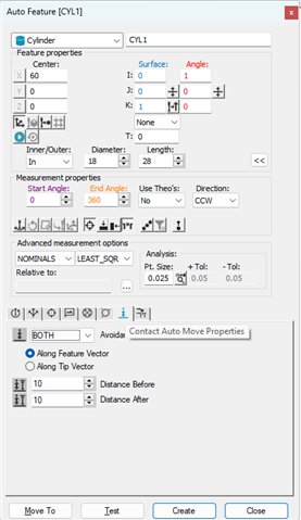
  • Many ways.  You can add move points, define a clearance cube / clear plane and activate it or turn on avoidance moves from inside the auto-feature dialog.  Since you're working with auto-features anyway, the easiest method would probably be to turn on avoidance moves....

  • Clearance planes are an amazing feature for this. 

    Clearp/ZPLUS,(height you want to move up from that code's current alignment's z origin, it won't change origins if you change alignments later), the second pass-through plane I don't trust, but it's supposed to allow you to clearplane effectively after a tip change. lol

    Then you need Move/Clearplane command inserted before/after each feature you want to avoid crashing the probe into an elevated surface.

    So your code will look like this:

    align/6dof locked down
    clearp/zplus,1,zplus,1,on
    move/clearplane
    feature
    move/clearplane
    feature
    move/clearplane
    etc

    If you want absolute coordinate control over your machine's movements, you can use Move/Increment.  If you move/increment up in z by an inch.  then call a second move/increment immediately after to traverse across x/y coordinate distance... the machine will move up an inch then move exactly as far as you tell it.   If you consolidate XYZ values in a single move increment, it will traverse a straight line "as the crow flies".

    Also there's move/point, which will be the same as increment, except it defines the xyz move coordinate relative to current alignment, instead of "move this distance from current position" (increment).

    Clearance plane will consolidate both the move/increments and utilize flymode (if you have it switched on) to cut the corners and make it a fluid movement between vector directions, instead of the move/increment's "move-stop-move" it will move the machine organically, without stopping between.

    Flymode takes a dump and doesn't work between multiple move increments, but it's awesome when combined with clearplanes or a defined clearcube.