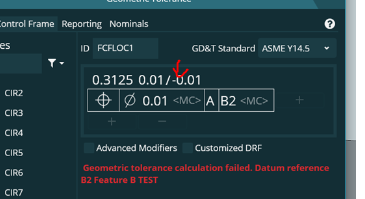
I am running 2022.2, and I could've sworn back in the day you could create a generic feature for Datums and use them as a callout.
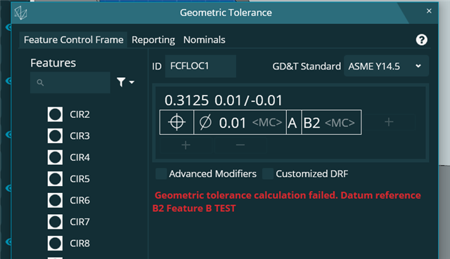
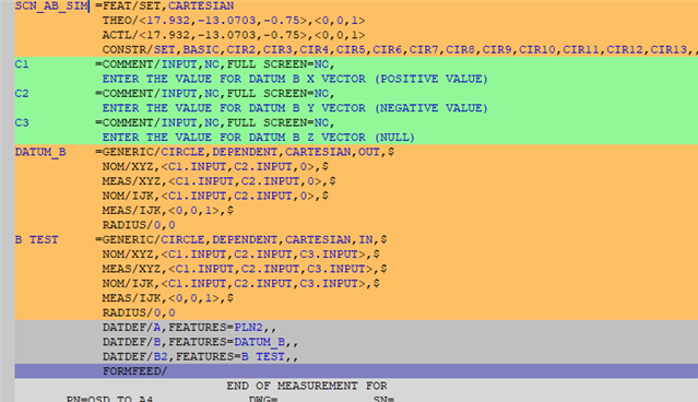
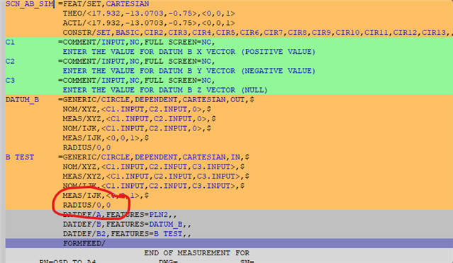
I am programming a part that has an unobtainable diameter on the 2nd side program, and to work around this I used a mid-feature that can be hit on both sides and planned to have hand-key values for the actual location of Datum B's centroid. After trying to make a test datum and callout, it will not let me use my theorized datum point as a tertiary. Any ideas on how to work around this? Before anyone mentions it, no I will not use equate alignment.
Current Code;
STARTUP =ALIGNMENT/START,RECALL:USE_PART_SETUP,LIST=YES
ALIGNMENT/END
MODE/MANUAL
PREHIT/0.08
RETRACT/0.08
FORMAT/TEXT,OPTIONS,ID,HEADINGS,SYMBOLS, ;NOM,TOL,MEAS,OUTTOL, , ,
MOVESPEED/ 500
LOADPROBE/DTC12_SM25-4_4X50
TIP/T1A0B0, SHANKIJK=0, 0, 1, ANGLE=0
COMMENT/OPER,NO,FULL SCREEN=YES,AUTO-CONTINUE=NO,OVC=NO,
SAW HORSE LOCATION IS CRITICAL TO THE FUNCTION OF THIS PROGRAM, REVIEW PROGRAM BOTTOM SIDE HIT LOCATION BEFORE PLACING PART ON SAWHORSES
PLN1 =FEAT/CONTACT/PLANE/DEFAULT,CARTESIAN,NONE,LEAST_SQR
THEO/<-29.8822,-6.802,24.375>,<0,0,1>
ACTL/<-29.8822,-6.802,24.375>,<0,0,1>
TARG/<-29.8822,-6.802,24.375>,<0,0,1>
ANGLE VEC=<1,0,0>,SQUARE
SHOW FEATURE PARAMETERS=NO
SHOW CONTACT PARAMETERS=NO
A1 =ALIGNMENT/START,RECALL:STARTUP,LIST=YES
ALIGNMENT/LEVEL,ZPLUS,PLN1
ALIGNMENT/TRANS,ZAXIS,PLN1
ALIGNMENT/END
PLN2 =FEAT/CONTACT/PLANE/DEFAULT,CARTESIAN,NONE,LEAST_SQR
THEO/<32,-3.0099,-2.0286>,<1,0,0>
ACTL/<32,-3.0099,-2.0286>,<1,0,0>
TARG/<32,-3.0099,-2.0286>,<1,0,0>
ANGLE VEC=<0,0,-1>,SQUARE
SHOW FEATURE PARAMETERS=NO
SHOW CONTACT PARAMETERS=NO
A2 =ALIGNMENT/START,RECALL:A1,LIST=YES
ALIGNMENT/ROTATE,XPLUS,TO,PLN2,ABOUT,ZPLUS
ALIGNMENT/END
CIR1 =FEAT/CONTACT/CIRCLE/DEFAULT,CARTESIAN,IN,LEAST_SQR
THEO/<-1.37,7.69,-0.25>,<0,0,1>,0.5007
ACTL/<-1.37,7.69,-0.25>,<0,0,1>,0.5007
TARG/<-1.37,7.69,-0.25>,<0,0,1>
START ANG=0,END ANG=360
ANGLE VEC=<1,0,0>
DIRECTION=CCW
SHOW FEATURE PARAMETERS=NO
SHOW CONTACT PARAMETERS=NO
A3 =ALIGNMENT/START,RECALL:A2,LIST=YES
ALIGNMENT/TRANS,XAXIS,CIR1
ALIGNMENT/TRANS,YAXIS,CIR1
ALIGNMENT/END
COMMENT/OPER,NO,FULL SCREEN=NO,AUTO-CONTINUE=NO,OVC=NO,
DCC ACTIVATED
MODE/DCC
CLEARP/ZPLUS,0.5,ZPLUS,0,ON
MOVE/CLEARPLANE
PLN3 =FEAT/CONTACT/PLANE/DEFAULT,CARTESIAN,NONE,LEAST_SQR
THEO/<-26.942,-8.7059,0>,<0,0,1>
ACTL/<-26.942,-8.7059,0>,<0,0,1>
TARG/<-26.942,-8.7059,0>,<0,0,1>
ANGLE VEC=<1,0,0>,SQUARE
SHOW FEATURE PARAMETERS=NO
SHOW CONTACT PARAMETERS=NO
A4 =ALIGNMENT/START,RECALL:A3,LIST=YES
ALIGNMENT/LEVEL,ZPLUS,PLN3
ALIGNMENT/TRANS,ZAXIS,PLN3
ALIGNMENT/END
MOVE/CLEARPLANE
PNT1 =FEAT/CONTACT/VECTOR POINT/DEFAULT,CARTESIAN
THEO/<3.7904,-19.575,-0.3391>,<0,1,0>
ACTL/<3.7904,-19.575,-0.3391>,<0,1,0>
TARG/<3.7904,-19.575,-0.3391>,<0,1,0>
SNAP=NO
SHOW FEATURE PARAMETERS=NO
SHOW CONTACT PARAMETERS=NO
MOVE/CLEARPLANE
PNT2 =FEAT/CONTACT/VECTOR POINT/DEFAULT,CARTESIAN
THEO/<28.506,-19.575,-0.4826>,<0,1,0>
ACTL/<28.506,-19.575,-0.4826>,<0,1,0>
TARG/<28.506,-19.575,-0.4826>,<0,1,0>
SNAP=NO
SHOW FEATURE PARAMETERS=NO
SHOW CONTACT PARAMETERS=NO
A5 =ALIGNMENT/START,RECALL:A4,LIST=YES
ALIGNMENT/ROTATE_CIRCLE,XPLUS,TO,PNT1,AND,PNT2,ABOUT,ZPLUS
ALIGNMENT/END
MOVE/CLEARPLANE
FLIP ORIGIN=FEAT/CONTACT/CIRCLE/DEFAULT,CARTESIAN,IN,LEAST_SQR
THEO/<0,0,-0.25>,<0,0,1>,0.5007
ACTL/<0,0,-0.25>,<0,0,1>,0.5007
TARG/<0,0,-0.25>,<0,0,1>
START ANG=0,END ANG=360
ANGLE VEC=<1,0,0>
DIRECTION=CCW
SHOW FEATURE PARAMETERS=NO
SHOW CONTACT PARAMETERS=NO
C1 =COMMENT/INPUT,NO,FULL SCREEN=NO,
ENTER THE VALUE FOR DATUM B X VECTOR (POSITIVE VALUE)
C2 =COMMENT/INPUT,NO,FULL SCREEN=NO,
ENTER THE VALUE FOR DATUM B Y VECTOR (NEGATIVE VALUE)
DATUM_B =GENERIC/POINT,DEPENDENT,CARTESIAN,$
NOM/XYZ,<0,0,0>,$
MEAS/XYZ,<C1.INPUT,C2.INPUT,0>,$
NOM/IJK,<0,0,1>,$
MEAS/IJK,<0,0,1>

