hexagon logo

Changing Setup and Running Program Causes Manual Alignment Problems

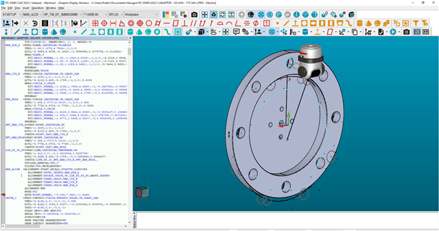
In the year or so I've been using pc-dmis I always have problems when I make a significant change to the way my part is fixtured and try to run a program. I have basically been starting over with a new program if I change the setup. However I recently put a lot of work into a program and dont want to start over so I'm trying to figure out how to do this correctly. Basically on this part I rotated the part 22.5° around the X axis from my original setup. When I measure the manual alignment features it doesn't line up with the CAD and ends up telling me the first dcc move is out of the stroke limit of my machine. I'm probably making a rookie mistake. I tried doing a cad transform and rotating the model 22.5° but that doesn't help. Thank you guys for your help.
Parents
  • When you transform a CAD model, it will not transform the program around it. What was the reason for the rotation, and why does it not reflect it in the code? I would remove the points and create a 2D line between the two diameter features, they're moot. When you say changing setup, what do you mean, you altered the location the part had on the CMM when it was originally programmed?

    How is the part fixtured? Why no clearance plane/cube? Have you tried using a step alignment where you take the feature and align right after, then next feature next align etc. ? Do you typically follow the CMM coordinate or is this based on a CNC coordinate?

    If it is showing as it is in the screen above, are you sure you're not using the wrong vector for the alignments? Typically on A90B90 head rotations you would want you Y value to be where the Z is. It is likely giving stroke limit because you're technically inside the granite with your probe. If you transform CAD do it before the program, you can import the original CAD file to wipe out any PCDMIS saved transformations.

  • Thanks. This will give me a lot to try. To answer the questions. 

    I rotated the part to make it easier to clock the parts the same way from one part to the next. I also changed several features since I decided to use magnets on one side of the part to give me more room on the other side to get features. 

    Probe is oriented a90b-90 first and then for the far side a90b90. Part is centered on two rolls and then up against 3 magnets on the far side. A couple of people on here advised against clearance cube so I havent used it. Step alignment have done on occasion but not doing it here, I will try that. The alignment is based on the cnc mill coordinates so I can tell the mill operator what directions he is off.

    I certainly could be using the wrong vector on the alignment, how would I check to see if I am? Thanks man

  • Ah gotcha, the rotation of the part won't change anything with those two probe orientations, it'll just clock the CMM to however you have it physically rotated. So the first feature is the centroid of the overall O.D. (Datum B) and then you use one of the .984" holes to clock it, is the alignment showing the rotation change based on which of the .984" features you have clocked in Y+ the best? Should almost look like the CAD rotates after that. Give the step alignment a go and see if it moves that trihegion around.

    I will look further later on, making dinner. Just a heads up, I followed someone who did a lot of XYZ matching from diff machines, I save my alignments at the end or take a picture of your setup so you don't ever get backwards. I like to make my alignment match my machine coordinate and get it moving in DCC, and then I will have a 2nd matching CNC or lathe or whatever to toggle from and be able to change back and forth. This makes visualizing setup and such on CMM easier in relation to part/machine coordinate.

  • I have had to do this to update programs for rev changes. I will preface this practice with the stipulation that my trihedron was already in the correct location in my cad before any alignments were made. At the start of the code and before any other alignments I inserted all the required features for the "new" alignment, then aligned to all of those features and hit "yes updated all following features" which then moved everything else to follow my new setup scheme. Then I started a new program, imported the model, picked up all my "new" DCC alignment features, then just pasted in the rest of the "corrected code" so everything was clean again.

    Your milage may vary as the Demon sometimes does wonky things.

    Also it looks like you're using a TP20 and magnets in your setup, I never had any issues using them, but strong magnetic fields are supposed to disable the sensors inside your probe.  

Reply
  • I have had to do this to update programs for rev changes. I will preface this practice with the stipulation that my trihedron was already in the correct location in my cad before any alignments were made. At the start of the code and before any other alignments I inserted all the required features for the "new" alignment, then aligned to all of those features and hit "yes updated all following features" which then moved everything else to follow my new setup scheme. Then I started a new program, imported the model, picked up all my "new" DCC alignment features, then just pasted in the rest of the "corrected code" so everything was clean again.

    Your milage may vary as the Demon sometimes does wonky things.

    Also it looks like you're using a TP20 and magnets in your setup, I never had any issues using them, but strong magnetic fields are supposed to disable the sensors inside your probe.  

Children
No Data