hexagon logo

Need help reporting Taper/foot of a Cone

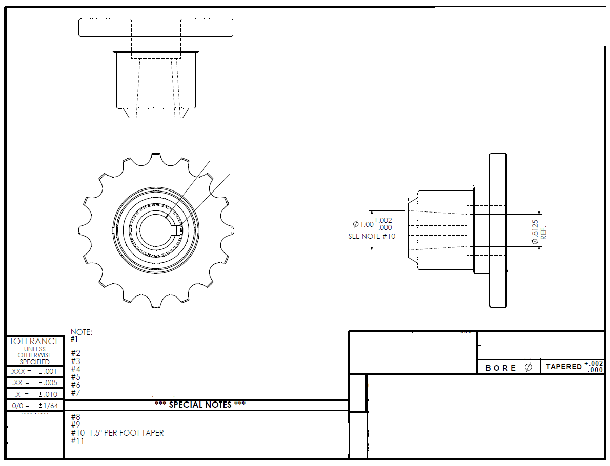
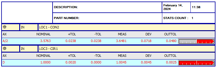
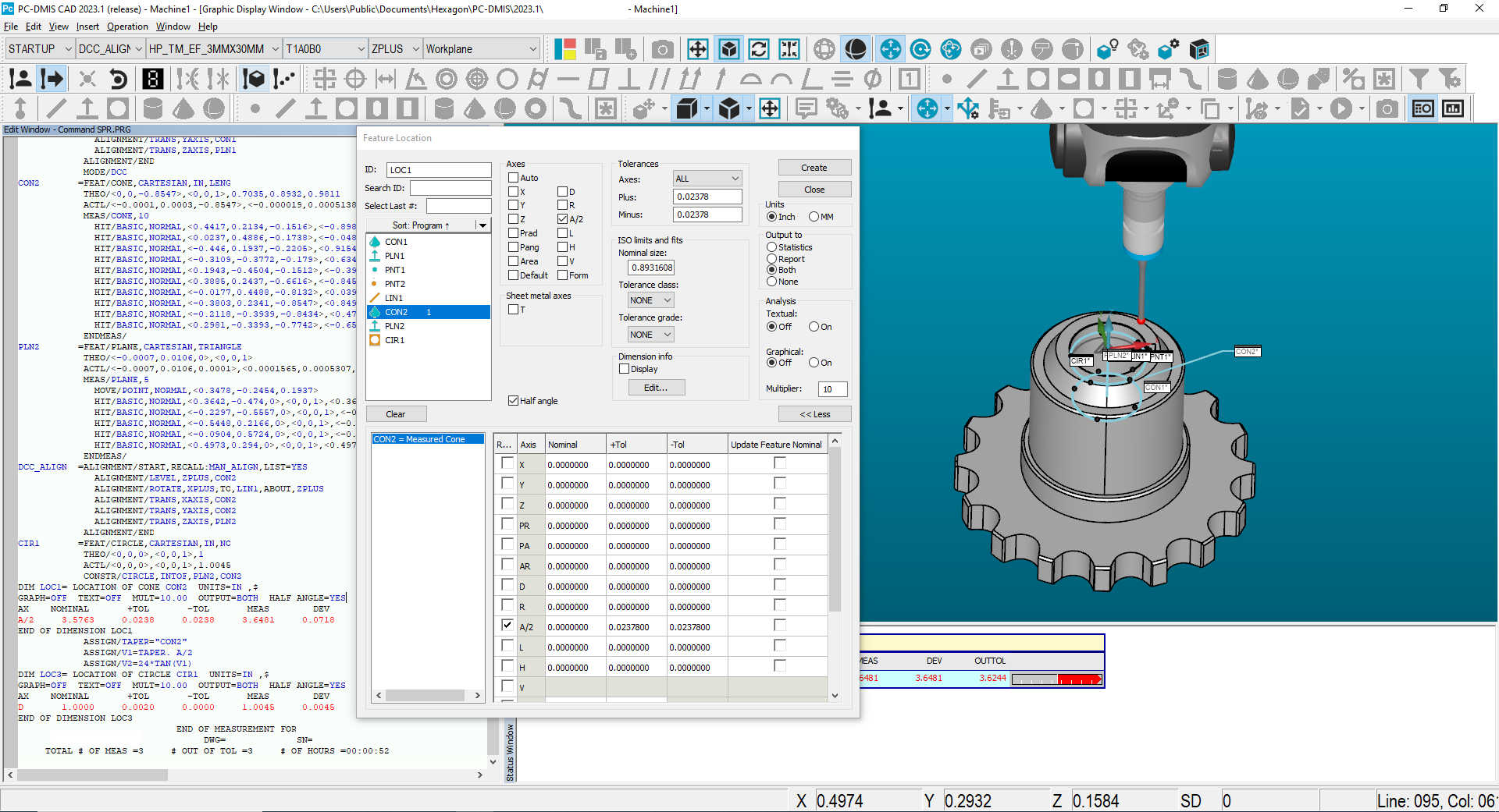
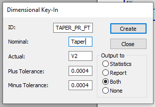
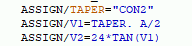
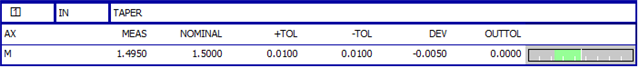
Hey guys. I am inspecting a part with a tapered bore. The drawing calls out '1.5" PER FOOT TAPER' with a tolerance block tolerance of ±.010. I measured the feature as a cone and my options are to report as an angle or half angle. I know that the half angle should be 3.5763. And to translate that to taper per foot I worked out the following equation: taper/foot = 24*tan(half angle). How can I implement this so that my report shows the measured taper/foot with a nominal of 1.500 ±.010? Currently I am reporting the half angle with a tolerance of ±.0238 which is what I calculated as .010"/foot taper as a half angle. Appreciate the help. 

  • Not sure if the Demon will let you... But maybe create a generic plane 6" above the part and project your cone on to that plane giving you a circle, which should reflect a radius change of your 1.5" per side per 12". As the angle changes so will the size of the projected circle, you could use cir.r.meas to create a formula to distil that data to a reported dimension of "1.5 +/-.01" 

  • This is a bit too wonky for me. There would be quite a bit of trig involved, and I wouldn't trust my results.

    I'm trying to assign a variable to the taper/foot calculation but I have no experience using variables on Pc-dmis. I'm thinking if I can pull the half angle from the cone and then plug that into my equation 24*tan(half-angle). After that assign the variable to the actual box in the key-in dimension. I have no idea if this is plausible.

    This is my code so far

  • Respectfully, i feel that note is not a feature of size controlled to the block tolerance.

    No matter how you slice or dice a ~1.5" long axis line... Multiplying or compounding 1/10th of the measured value, to equate to a repeatable result that will discern a ±0.010 tolerance is an impossible ask.  You are multiplying your uncertainty of cone angle to equivalate it to that 1.5" along a 12" ratio.  Cone angle is very difficult to control on a cmm.

    The engineer either needs to change the spec to tolerance it as an angle form centerline as you are doing ± a relevant angular allowance or go back to school.

    Another consideration, the print has that "Bore diameter | Tapered +0.002/-0.000" 
    --Is that the intended "TAPERED" cone tolerance?  

    If so, construct a 1.5" taper along a 12" line angle, at the nominal bore diameter (consider it as a BASIC value).  measure t values from that line.  Tolerance the t-values as +0.001 / -0.000 (radius of the diametrical tol) repeat radially like 4 times about a few spots down the tapered bore

  • That can work, instead of putting "Taper" and "V2" in there, create an assign statement before the Key-in, and just hit "Create" on the popup, the fields will display the actual number values. The report will as well. I just hard types values, but you'd change the Variables to your formulas. Your TAPER="CON2" will just display the text CON2. I think you're wanting 

    TAPER = CON2.TA/2 or just put in 1.500 since that is the nominal.

    V1 = CON2.A/2

                ASSIGN/NOM_TAPER=1.5
                ASSIGN/MEAS_TAPER=1.495
    DIM TAPER= KEYED IN DIMENSION  OUTPUT=BOTH
    AX       MEAS    NOMINAL       +TOL       -TOL        DEV     OUTTOL
    M    MEAS_TAPER  NOM_TAPER     0.0100     0.0100    -0.0050     0.0000 --#------

  • It does feel odd applying the block tolerance to a dimension in a note, but I think it is the most reasonable conclusion. I believe that the 'bore Ø tapered +.002/-.000" tolerance applies to the 1.000 dimension at the big end of the taper which is toleranced similarly on the side view. Since the small end of the taper is only reference the tolerance has to be applied to the taper itself. This is simply my conclusion as a new engineer with limited experience.

  • I can tell you have quite a bit of experience with this sort of thing, and what you say about multiplying the uncertainty along a short length makes sense, so my question for you is would you reject these for the taper measuring 1.530"/foot? That is what the measured angle works out to. I am quite confident in this result, I have checked several parts and checked the same part multiple times and get anywhere from 1.527/foot to 1.531/foot.

  • Works beautifully brother. Thank you. This is my final code:

                ASSIGN/NOM_TAPER=1.500
                ASSIGN/TAPER="CON2"
                ASSIGN/V1=TAPER.ANGLE/2/57.2958
                ASSIGN/V2=24*TAN(V1)
    DIM TAPER_FT= KEYED IN DIMENSION  OUTPUT=BOTH
    AX    NOMINAL       +TOL       -TOL       MEAS        DEV     OUTTOL
    M    NOM_TAPER     0.0100     0.0100  V2     0.0241     0.0141 -------->

  • In my experience, when I'm uncertain with what the machine is spitting out, I do a "sanity check" on a surface plate with a sine block and an indicator.

    That way you can say with absolute confidence, what the demon is telling you, is in the ballpark.  Plus, you can keep product moving at the same time.

    the time/effort you need to invest into extrapolating that dimension on the CMM might be more than just checking it the good ol' fashioned way.

  • How about you construct a circle 12" from the cone apex and report the diameter?

  • Apparently, that's too "wonky" for this instance. I try to always fall back to the KISS principal though.