hexagon logo

Beginner Help with Multiple Alignments

I am measuring a mold cavity that is not supported with 3D CAD so I'm having to do more work manually on the machine. I did my manual and auto alignment with a plane and two dowel holes on the part. This alignment allowed me to do some measurements of the molding surface, and generate a line midpoint that I was going to use as my new XY zero, or A3. Like all new adventures, something has gone wrong. My Y position on A3 is out by about 45mm. I acknowledge that this is operator error but I cant find a mistake. Is there a limit to how many alignments you can do or some protocol that I have not discovered yet?

Thanks in advance, Glenn

  • Don't think so.
    Post your code here so the folks can see it. Use Insert/code from below.

    TARTUP    =ALIGNMENT/START,RECALL:USE_PART_SETUP,LIST=YES
                ALIGNMENT/END
                MODE/MANUAL
                FORMAT/TEXT,OPTIONS, ,HEADINGS,SYMBOLS, ;NOM,TOL,MEAS,DEV,OUTTOL, , 
                TEMPCOMP/METHOD = AUTOMATIC,MATERIAL = Iron,CTE=11.3
                  ,SET WARNING LIMIT = FALSE,MINIMUM = 10,MAXIMUM = 40
                  ,PART SENSOR NUM=DEFAULT,X SCALE= 20,Y SCALE= 20,Z SCALE= 20,PART TEMP=20
                LOADPROBE/T3_8X200
                WORKPLANE/ZPLUS
                TIP/T1A0B0, SHANKIJK=0, 0, 1, ANGLE=90
    PNT1       =FEAT/POINT,CARTESIAN
                THEO/<0,414,18>,<0,0,1>
                ACTL/<0,414,18>,<0,0,1>
                READPOINT/
    A1         =ALIGNMENT/START,RECALL:STARTUP,LIST=YES
                  ALIGNMENT/TRANS,XAXIS,PNT1
                  ALIGNMENT/TRANS,YAXIS,PNT1
                  ALIGNMENT/TRANS,ZAXIS,PNT1
                  ALIGNMENT/TRANS,YAXIS,PNT1
                  ALIGNMENT/TRANS_OFFSET,YAXIS,-414
                  ALIGNMENT/TRANS,ZAXIS,PNT1
                  ALIGNMENT/TRANS_OFFSET,ZAXIS,-18
                ALIGNMENT/END
    CIR1       =FEAT/CONTACT/CIRCLE/DEFAULT,CARTESIAN,IN,LEAST_SQR
                THEO/<0,414,18>,<0,0,1>,24.5
                ACTL/<0,414,18>,<0,0,1>,24.5
                TARG/<0,414,18>,<0,0,1>
                START ANG=0,END ANG=360
                ANGLE VEC=<1,0,0>
                DIRECTION=CCW
                SHOW FEATURE PARAMETERS=NO
                SHOW CONTACT PARAMETERS=YES
                  NUMHITS=4,DEPTH=7,PITCH=0
                  SAMPLE METHOD=SAMPLE_HITS
                  SAMPLE HITS=0,SPACER=-10
                  AVOIDANCE MOVE=AFTER,DISTANCE=25
                  FIND HOLE=DISABLED,ONERROR=NO,READ POS=NO
                SHOW HITS=YES
                  HIT/BASIC,<12.25,414,11>,<-1,0,0>,<12.25,414,11>
                  HIT/BASIC,<0,426.25,11>,<0,-1,0>,<0,426.25,11>
                  HIT/BASIC,<-12.25,414,11>,<1,0,0>,<-12.25,414,11>
                  HIT/BASIC,<0,401.75,11>,<0,1,0>,<0,401.75,11>
                ENDMEAS/
    A2         =ALIGNMENT/START,RECALL:A1,LIST=YES
                  ALIGNMENT/TRANS,XAXIS,CIR1
                  ALIGNMENT/TRANS,YAXIS,CIR1
                  ALIGNMENT/TRANS,YAXIS,CIR1
                  ALIGNMENT/TRANS_OFFSET,YAXIS,-414
                ALIGNMENT/END
    PNT2       =FEAT/CONTACT/VECTOR POINT/DEFAULT,CARTESIAN
                THEO/<25.304,412.973,18>,<0,0,1>
                ACTL/<25.304,412.973,18>,<0,0,1>
                TARG/<25.304,412.973,18>,<0,0,1>
                SNAP=NO
                SHOW FEATURE PARAMETERS=NO
                SHOW CONTACT PARAMETERS=YES
                  AVOIDANCE MOVE=BOTH,DISTANCE=10
                SHOW HITS=YES
                  HIT/BASIC,<25.304,412.973,18>,<0,0,1>,<25.304,412.973,18>
                ENDMEAS/
    A3         =ALIGNMENT/START,RECALL:A2,LIST=YES
                  ALIGNMENT/TRANS,ZAXIS,PNT2
                  ALIGNMENT/TRANS,ZAXIS,PNT2
                  ALIGNMENT/TRANS_OFFSET,ZAXIS,-18
                ALIGNMENT/END

  • It is hard to work on something without CAD as I did 2 years ago.  as  said, post you code so others could help you.

  • Its hard for me to post my code because my CMM has to run independent of our network due to some overly complex security protocols here. But, based on the response, I can "leap frog" a new alignment (A3) based on geometry I have created within the previous alignment (A2)? As long as that is a true statement, I will spend the time to find my mistake. I probably selected the wrong feature when defining my A3. Thanks for the confirmation.

  • I would not leapfrog on a CMM if the part fits within the volume of the machine. 
    It sounds like there is an error in your alignments or a bad hit somewhere. 
    Try doing it again, 3 hits for a plane, 4 hits for each circle, create a line between the circles. Do your first alignment as...
    Level plane to Z
    Set Z origin to plane
    Set XY origin to one of the circles
    Rotate X or Y to the line (whichever is appropriate for your setup)

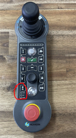
    Once that is done, assuming your using a Hexagon machine with a NextJogBox, hit the button to change to "part" coordinates and slowly move the probe around and see if its following your parts direction. If you move between the dowel holes your machine should move in a straight line in whichever axis your rotated to.

  • As   said it looks like standard 3-2-1 Alignment scenario. perform a progressive alignment (Level, Rotate & origin step by step in each alignment) by which you are able to notice where you are going wrong. The number of alignments may increase but believe me it's clear and easy to understand. Make sure your theoretical inputs are correct for XYZ & IJK.

  •   I agree with you 100%,

    I also create each subsequent alignment on STARTUP, it helps me not to repeat the error or if sometimes I have to go back and change something in the alignment, because e.g. Revision has changed and corrections need to be made or if something went wrong.