hexagon logo

Common Datums

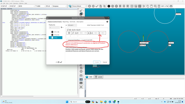
Most are already probably aware, but I'm talking about the option in Geo Tol to construct a common datum. So if I have B-C for example, I should define each as a datum, then choose common datum and finally select B and C. My understanding is that pcdmis will square to that common datum. The FCF may look something like |A|B-C|C|. I had Hexagon Apps support on site for two days and he could not get that to work. I'm concerned that if he couldn't get it to work that he may have given me bad information. Either way, I cannot get that to work.

Thank You

Parents
  • Can you share a drawing?  I need to see what the datums are defined as and how they are called out.  It may be that the way it's depicted on the drawing isn't correct.  For example, If A is a plane and B & C are cylinders perpendicular to that plane (think of a face with two dowel holes in it for example), then A controls three degrees of freedom (two rotations and one translation), B-C controls the final degree of rotation about the plane and the remaining two translations, making the addition of C as a tertiary redundant.

  • I can't post the print but I can tell you the plane and two dowels are all facing the same axis. In a legacy alignment I would level to the plane, square to the two dowels and zero on one of them. Is my understanding of the common datum function correct?

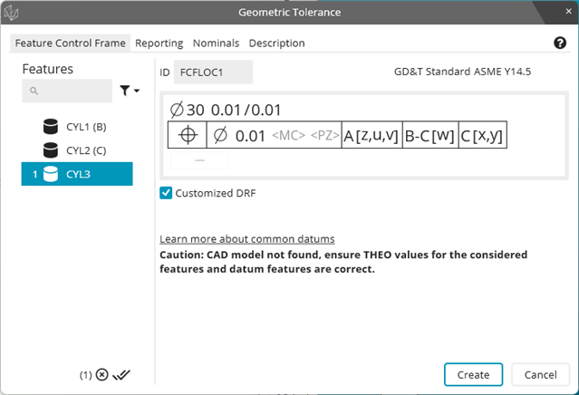
  • Datum reference frames function differently to traditional alignments.  They behave like a hard gauge and follow datum precedence rules.  Each datum must constrain as many degrees of freedom as it is capable of doing, that is why you see an error for this DRF when you try to add C as a tertiary (see my previous explanation).  

    The only way you could add C would be to select "customized DRF" and override the natural constraints but that would be going against what is defined in the standard.

    As always, you should seek clarification of design intent from your customer / whoever issued the drawing. 

Reply
  • Datum reference frames function differently to traditional alignments.  They behave like a hard gauge and follow datum precedence rules.  Each datum must constrain as many degrees of freedom as it is capable of doing, that is why you see an error for this DRF when you try to add C as a tertiary (see my previous explanation).  

    The only way you could add C would be to select "customized DRF" and override the natural constraints but that would be going against what is defined in the standard.

    As always, you should seek clarification of design intent from your customer / whoever issued the drawing. 

Children