hexagon logo

Odd issue when aligning part

PNT1       =FEAT/CONTACT/VECTOR POINT/DEFAULT,CARTESIAN
            THEO/<-2.6744,0.8146,0.938>,<0,0,1>
            ACTL/<-2.6744,0.8146,0.938>,<0,0,1>
            TARG/<-2.6744,0.8146,0.938>,<0,0,1>
            SHOW FEATURE PARAMETERS=NO
            SHOW CONTACT PARAMETERS=YES
              AVOIDANCE MOVE=NO
            SHOW HITS=NO
CIR1       =FEAT/CONTACT/CIRCLE/DEFAULT,CARTESIAN,IN,LEAST_SQR
            THEO/<-2.9518,1.2227,0.438>,<0,0,1>,0.201
            ACTL/<-2.9518,1.2227,0.438>,<0,0,1>,0.201
            TARG/<-2.9518,1.2227,0.438>,<0,0,1>
            START ANG=0,END ANG=360
            ANGLE VEC=<1,0,0>
            DIRECTION=CCW
            SHOW FEATURE PARAMETERS=NO
            SHOW CONTACT PARAMETERS=YES
              NUMHITS=3,DEPTH=0.02,PITCH=0
              SAMPLE METHOD=SAMPLE_HITS
              SAMPLE HITS=0,SPACER=0
              AVOIDANCE MOVE=NO
              FIND HOLE=DISABLED,ONERROR=NO,READ POS=NO
            SHOW HITS=NO
CIR2       =FEAT/CONTACT/CIRCLE/DEFAULT,CARTESIAN,IN,LEAST_SQR
            THEO/<2.9518,-1.2227,0.438>,<0,0,1>,0.201
            ACTL/<2.9518,-1.2227,0.438>,<0,0,1>,0.201
            TARG/<2.9518,-1.2227,0.438>,<0,0,1>
            START ANG=0,END ANG=360
            ANGLE VEC=<1,0,0>
            DIRECTION=CCW
            SHOW FEATURE PARAMETERS=NO
            SHOW CONTACT PARAMETERS=YES
              NUMHITS=3,DEPTH=0.02,PITCH=0
              SAMPLE METHOD=SAMPLE_HITS
              SAMPLE HITS=0,SPACER=0
              AVOIDANCE MOVE=NO
              FIND HOLE=DISABLED,ONERROR=NO,READ POS=NO
            SHOW HITS=NO
A1         =ALIGNMENT/START,RECALL:STARTUP,LIST=YES
              ALIGNMENT/TRANS,ZAXIS,PNT1
              ALIGNMENT/ROTATE_CIRCLE,XPLUS,TO,CIR1,AND,CIR2,ABOUT,ZPLUS
              ALIGNMENT/TRANS,XAXIS,CIR1
              ALIGNMENT/TRANS,YAXIS,CIR1
            ALIGNMENT/END
            CHECK/0.5,1
            MOVESPEED/ 250
            PREHIT/0.2
            RETRACT/0.2
            TOUCHSPEED/ 3
            COMMENT/OPER,NO,FULL SCREEN=NO,AUTO-CONTINUE=NO,OVC=NO,
            DCC Starts Here
            MODE/DCC
CIR3       =FEAT/CONTACT/CIRCLE/DEFAULT,CARTESIAN,IN,LEAST_SQR
            THEO/<3.195,0,-0.232>,<0,0,1>,5.25
            ACTL/<3.195,0,-0.232>,<0,0,1>,5.25
            TARG/<3.195,0,-0.232>,<0,0,1>
            START ANG=0,END ANG=360
            ANGLE VEC=<0.9238795,0.3826834,0>
            DIRECTION=CCW
            SHOW FEATURE PARAMETERS=NO
            SHOW CONTACT PARAMETERS=YES
              NUMHITS=5,DEPTH=0.1,PITCH=0
              SAMPLE METHOD=SAMPLE_HITS
              SAMPLE HITS=0,SPACER=0
              AVOIDANCE MOVE=BOTH,DISTANCE BEFORE=0.3937,DISTANCE AFTER=0.3937,DIRECTION=ALONG FEATURE VECTOR
              FIND HOLE=DISABLED,ONERROR=NO,READ POS=NO
            SHOW HITS=NO
PLN1       =FEAT/CONTACT/PLANE/ADAPTIVE_PLANE_CIRCLE_SCAN,CARTESIAN,NONE,LEAST_SQR
            THEO/<3.195,0,0>,<0,0,1>
            ACTL/<3.195,0,0>,<0,0,1>
            TARG/<3.195,0,0>,<0,0,1>
            ANGLE VEC=<0.9238795,0.3826834,0>,SQUARE
            SHOW FEATURE PARAMETERS=NO
            SHOW CONTACT PARAMETERS=YES
              NUMHITS=445,NUMROWS=3
              SPACER=0
              AVOIDANCE MOVE=NO
            SHOW HITS=NO
CIR4       =FEAT/CONTACT/CIRCLE/ADAPTIVE_CIRCLE_SCAN,CARTESIAN,IN,LEAST_SQR
            THEO/<0,0,-0.5>,<0,0,1>,0.201
            ACTL/<0,0,-0.5>,<0,0,1>,0.201
            TARG/<0,0,-0.5>,<0,0,1>
            START ANG=0,END ANG=360
            ANGLE VEC=<0.9238795,0.3826834,0>
            DIRECTION=CCW
            SHOW FEATURE PARAMETERS=NO
            SHOW CONTACT PARAMETERS=YES
              NUMHITS=35,DEPTH=0.1,PITCH=0
              SAMPLE METHOD=SAMPLE_HITS
              SAMPLE HITS=0,SPACER=0
              AVOIDANCE MOVE=BOTH,DISTANCE BEFORE=0.3937,DISTANCE AFTER=0.3937,DIRECTION=ALONG FEATURE VECTOR
              FIND HOLE=DISABLED,ONERROR=NO,READ POS=NO
            SHOW HITS=NO
CIR5       =FEAT/CONTACT/CIRCLE/ADAPTIVE_CIRCLE_SCAN,CARTESIAN,IN,LEAST_SQR
            THEO/<6.39,0,-0.5>,<0,0,1>,0.201
            ACTL/<6.39,0,-0.5>,<0,0,1>,0.201
            TARG/<6.39,0,-0.5>,<0,0,1>
            START ANG=0,END ANG=360
            ANGLE VEC=<0.9238795,0.3826834,0>
            DIRECTION=CCW
            SHOW FEATURE PARAMETERS=NO
            SHOW CONTACT PARAMETERS=YES
              NUMHITS=35,DEPTH=0.1,PITCH=0
              SAMPLE METHOD=SAMPLE_HITS
              SAMPLE HITS=0,SPACER=0
              AVOIDANCE MOVE=BOTH,DISTANCE BEFORE=0.3937,DISTANCE AFTER=0.3937,DIRECTION=ALONG FEATURE VECTOR
              FIND HOLE=DISABLED,ONERROR=NO,READ POS=NO
            SHOW HITS=NO
CIR6       =FEAT/CONTACT/CIRCLE/ADAPTIVE_CIRCLE_SCAN,CARTESIAN,IN,LEAST_SQR
            THEO/<3.195,0,-0.232>,<0,0,1>,5.25
            ACTL/<3.195,0,-0.232>,<0,0,1>,5.25
            TARG/<3.195,0,-0.232>,<0,0,1>
            START ANG=0,END ANG=360
            ANGLE VEC=<0.9238795,0.3826834,0>
            DIRECTION=CCW
            SHOW FEATURE PARAMETERS=NO
            SHOW CONTACT PARAMETERS=YES
              NUMHITS=181,DEPTH=0.1,PITCH=0
              SAMPLE METHOD=SAMPLE_HITS
              SAMPLE HITS=0,SPACER=0
              AVOIDANCE MOVE=BOTH,DISTANCE BEFORE=0.3937,DISTANCE AFTER=0.3937,DIRECTION=ALONG FEATURE VECTOR
              FIND HOLE=DISABLED,ONERROR=NO,READ POS=NO
            SHOW HITS=NO
A2         =ALIGNMENT/START,RECALL:A1,LIST=YES
              ALIGNMENT/LEVEL,ZPLUS,PLN1
              ALIGNMENT/TRANS,ZAXIS,PLN1
              ALIGNMENT/ROTATE_CIRCLE,XPLUS,TO,CIR4,AND,CIR5,ABOUT,ZPLUS
              ALIGNMENT/TRANS,XAXIS,CIR6
              ALIGNMENT/TRANS,YAXIS,CIR6
            ALIGNMENT/END
$$ NO,
            Main Alignments end here

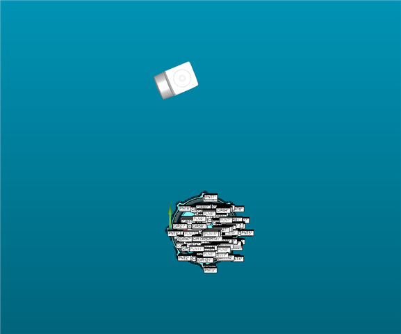
I had something odd happen the other day when making a program. I imported my cad, did my basic transforming to align it the way I would be holding it. After the first alignment I noticed that the head of my cmm in the graphical window was no long perpendicular but at a weird angle. I went through and checked my alignments and couldn't see anything wrong. Iv attached a picture and a copy of my code. 

Any help would be appreciated

Parents
  • A rotation rotates around the actual origin, but in your manual alignment you don’t define an origin in X/Y before you rotate around it, only afterwards. So your manual alignment rotates around the machine origin and your DCC alignment rotates around the manual alignment origin. That can’t work. 

  • The text below is from the hexagon help site for PC-DMIS. This is the order I follow when I align. I have heard of other people doing it different ways. In my mind if the people who design the software say to do something a certain way I feel like that's the best way.

    LEVEL

    Constrains two degrees of rotation such that the leveled axis matches the vector of the selected feature.

    This will always be the primary datum and must be a 3D feature with a vector.

    Typical Features: Plane, Cylinder, Cone, or a constructed 3D feature.

    ROTATE

    Constrains one degree of rotation about the leveled axis such that the rotated axis matches the vector of the selected feature.

    This will always be the secondary or tertiary datum and must be a 2D or 3D feature with a vector.

    Typical Features: Plane, Line, Cylinder, Cone, or a constructed 2D/3D feature.

    You can also select any two-point type features to simulate a line that can be used to rotate. These can be two points, two circles, two spheres, or a combination thereof. The direction of the simulated line is based on the order of the selected features.

    ORIGIN

    Constrains three degrees of translation (origin) in X, Y, and Z-axis.

    This sets the origin on primary, secondary, and tertiary datums or as per drawing requirements.

    Typical Features: Any feature.

Reply
  • The text below is from the hexagon help site for PC-DMIS. This is the order I follow when I align. I have heard of other people doing it different ways. In my mind if the people who design the software say to do something a certain way I feel like that's the best way.

    LEVEL

    Constrains two degrees of rotation such that the leveled axis matches the vector of the selected feature.

    This will always be the primary datum and must be a 3D feature with a vector.

    Typical Features: Plane, Cylinder, Cone, or a constructed 3D feature.

    ROTATE

    Constrains one degree of rotation about the leveled axis such that the rotated axis matches the vector of the selected feature.

    This will always be the secondary or tertiary datum and must be a 2D or 3D feature with a vector.

    Typical Features: Plane, Line, Cylinder, Cone, or a constructed 2D/3D feature.

    You can also select any two-point type features to simulate a line that can be used to rotate. These can be two points, two circles, two spheres, or a combination thereof. The direction of the simulated line is based on the order of the selected features.

    ORIGIN

    Constrains three degrees of translation (origin) in X, Y, and Z-axis.

    This sets the origin on primary, secondary, and tertiary datums or as per drawing requirements.

    Typical Features: Any feature.

Children