hexagon logo

Dimension from theoretical pin

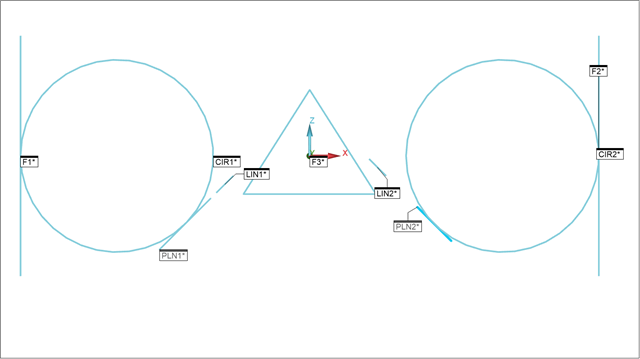
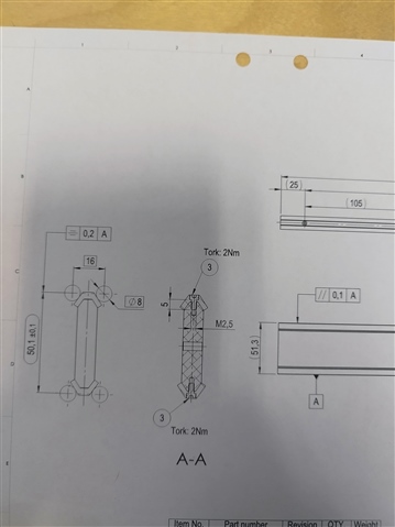
Hi i have this part and i need to measure the 50.1 dimension.

Im not sure how to go about to construct the Ø8 pins where the tangent the guide rail.

Can i measure this in cmm or do i need to build a checking fixture? ty you all

Parents
  • I would use a check fixture for the Ø8mm basics.  One would be a base that the part sits on, and the other would be a hat that sits on top of the part.  Then measure the center of the diameters with a height gage.  You'd have to be careful that the part is perfectly vertical, and the pin p

    Or, have one solid and one movable pair mounted to a plate so the Ø8mm pins act like a vise.  Then mount a dial indicator to it to measure the 50.1mm dimension.

    What I don't think will work is the symmetry dimension.  I'm no genius when it comes to ISO dimensioning, but I'm pretty sure the datum needs to be in the center of the feature for the feature to be symmetrical to it.  Your Datum A is a plane on the bottom of the part when it should be a center plane or width.

Reply Children
  • It might be.  You would need to measure the four faces that touch the Ø8mm basic circles, construct generic circles at 8mm and 16mm apart, fit them tangent to the top and bottom of the part, then measure the distance between each pair of circles.  Is it possible, probably.  Do I know how to code such an optimization problem, no.  Because I don't know how to do that, and I do know how to use a height gage I would just measure the feature on the rock.

    Alternatively, I do know how to use Solidworks.  I could report the position and vector of each face and draw them in CAD software.  Then I could use the drawing constraints to construct the 8mm circles and dimension the distance between them.

  • I have done this for gage diameters, but never for a gauge "line".
    Slightly confused with their use of symmetry as related to datum A which looks like is half of the thing that needs to be symmetrical.

    This would be hard to do though, and I hope your machining department can hit that, it's a pretty tight tolerance due to any cutter error being multiplied 4x.

    It might be easier and much more reliable to have your tooling guy whip you up some custom C-channel shaped blocks, then you could toss in your 8mm gage pins and are constrained to the correct spacing and forced apart by the wedge shape between them. Then proceed to check it with a height gage (would also give the shop monkeys a way to actually check it themselves)
     

  • Assuming your section A-A view is looking down the Y axis, you would need to measure the two planar faces and then intersect them with a generic plane (YPLUS vector) to give you two lines.  You would then need to construct another two generic lines, one at X-12 and one at X+12.  You can then create two circles, tangential to the lines as shown below...

    PLN1       =FEAT/CONTACT/PLANE/DEFAULT,CARTESIAN,OUTLINE,LEAST_SQR
                THEO/<-5.172,0,-2.828>,<-0.7071068,0,0.7071068>
                ACTL/<-5.172,0,-2.828>,<-0.7071068,0,0.7071068>
                TARG/<-5.172,0,-2.828>,<-0.7071068,0,0.7071068>
                ANGLE VEC=<0.7071068,0,-0.7071068>,SQUARE
                SHOW FEATURE PARAMETERS=NO
                SHOW CONTACT PARAMETERS=YES
                  NUMHITS=2,NUMROWS=2
                  SPACER=3
                  AVOIDANCE MOVE=BOTH,DISTANCE BEFORE=10,DISTANCE AFTER=10,DIRECTION=ALONG FEATURE VECTOR
                  USE BOUNDARY OFFSET=NO
                SHOW HITS=NO
    PLN2       =FEAT/CONTACT/PLANE/DEFAULT,CARTESIAN,OUTLINE,LEAST_SQR
                THEO/<5.172,0,-2.828>,<0.7071068,0,0.7071068>
                ACTL/<5.172,0,-2.828>,<0.7071068,0,0.7071068>
                TARG/<5.172,0,-2.828>,<0.7071068,0,0.7071068>
                ANGLE VEC=<0.7071068,0,-0.7071068>,SQUARE
                SHOW FEATURE PARAMETERS=NO
                SHOW CONTACT PARAMETERS=YES
                  NUMHITS=2,NUMROWS=2
                  SPACER=2
                  AVOIDANCE MOVE=BOTH,DISTANCE BEFORE=10,DISTANCE AFTER=10,DIRECTION=ALONG FEATURE VECTOR
                  USE BOUNDARY OFFSET=NO
                SHOW HITS=NO
    F1         =GENERIC/LINE,DEPENDENT,CARTESIAN,$
                NOM/XYZ,<-12,0,0>,$
                MEAS/XYZ,<-12,0,0>,$
                NOM/IJK,<0,0,1>,$
                MEAS/IJK,<0,0,1>,$
                DISTANCE/10,10
    F2         =GENERIC/LINE,DEPENDENT,CARTESIAN,$
                NOM/XYZ,<12,0,0>,$
                MEAS/XYZ,<12,0,0>,$
                NOM/IJK,<0,0,-1>,$
                MEAS/IJK,<0,0,-1>,$
                DISTANCE/10,10
    F3         =GENERIC/PLANE,DEPENDENT,CARTESIAN,$
                NOM/XYZ,<0,0,0>,$
                MEAS/XYZ,<0,0,0>,$
                NOM/IJK,<0,1,0>,$
                MEAS/IJK,<0,1,0>
    LIN1       =FEAT/LINE,CARTESIAN,UNBOUNDED,NO
                THEO/<-3.172,0,-0.828>,<-0.7071068,0,-0.7071068>
                ACTL/<-3.172,0,-0.828>,<-0.7071068,0,-0.7071068>
                CONSTR/LINE,INTOF,PLN1,F3
    LIN2       =FEAT/LINE,CARTESIAN,UNBOUNDED,NO
                THEO/<3.172,0,-0.828>,<-0.7071068,0,0.7071068>
                ACTL/<3.172,0,-0.828>,<-0.7071068,0,0.7071068>
                CONSTR/LINE,INTOF,PLN2,F3
                WORKPLANE/YPLUS
    CIR1       =FEAT/CIRCLE,CARTESIAN,OUT,NO
                THEO/<-8,0,0>,<0,1,0>,8
                ACTL/<-8,0,0>,<0,1,0>,8
                CONSTR/CIRCLE,TANLINES,F1,LIN1,
    CIR2       =FEAT/CIRCLE,CARTESIAN,OUT,NO
                THEO/<8,0,0>,<0,1,0>,8
                ACTL/<8,0,0>,<0,1,0>,8
                CONSTR/CIRCLE,TANLINES,F2,LIN2,