hexagon logo

How to generate lots of points on a freeform surface?

I need to measure a freeform surface on an injection mold core. The surface is not a cone, sphere or plane. I think I can use "feature set" to define the surface from a quantity of points and then use the profile of surface dimension to compare the results to the CAD model. I do not have a scanning head on the CMM. I cant find an efficient way to generate the points on the surface. I can select the feature on the CAD model and it highlights within its boundaries so I would think that there must be a way to simply apply a grid of points to the highlighted region. What is the best way to do this? Thanks in advance.

Parents
  • I have CAD++ and I have a DCC command in the program. I'm probably doing something wrong but if I understand correctly, the scan function will command the CMM to generate hits within the described grid even without a scanning head? That would be very useful for me so I need to learn how to do it. Thanks again. Glenn

  • If you have CAD++ you should have the scanning options.

    Even without a scanning probe you can define touch trigger point scans.

    For your applicatiuon there are two options.

    UV scan - will create a grid pattern of points on a CAD surface (or surfaces).  For this option you select the CAD surface(s) and PC-Dmis displays an internal co-ord system for each surface (with a U and V direction).  You can then specify how many hits in each direction, plus an offset in from the edge (in each direction, done as a value from 0 to 1).  The main issue with this is if you have multiple surfaces of different sizes you get a varying density of points across the surfaces.

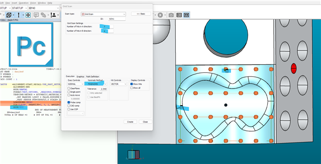
    My proffered option however is the Grid scan - this is similar and can work across multiple surfaces, but instead of each surface getting it's own UV axis system, you select the required surfaces, then drag a rectangle in the graphics window (which will give you an A and B direction).

    You then specify number of hits in each direction (A and B) and you get an even spread of hits over selected surfaces within the rectangle.

    Note, for some reason these always default to MASTER (make sure to change to FIND NOMS).

Reply
  • If you have CAD++ you should have the scanning options.

    Even without a scanning probe you can define touch trigger point scans.

    For your applicatiuon there are two options.

    UV scan - will create a grid pattern of points on a CAD surface (or surfaces).  For this option you select the CAD surface(s) and PC-Dmis displays an internal co-ord system for each surface (with a U and V direction).  You can then specify how many hits in each direction, plus an offset in from the edge (in each direction, done as a value from 0 to 1).  The main issue with this is if you have multiple surfaces of different sizes you get a varying density of points across the surfaces.

    My proffered option however is the Grid scan - this is similar and can work across multiple surfaces, but instead of each surface getting it's own UV axis system, you select the required surfaces, then drag a rectangle in the graphics window (which will give you an A and B direction).

    You then specify number of hits in each direction (A and B) and you get an even spread of hits over selected surfaces within the rectangle.

    Note, for some reason these always default to MASTER (make sure to change to FIND NOMS).

Children