hexagon logo

Alignment Rotation Question

Good morning,

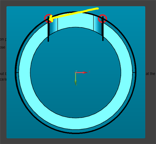
I have a quick question regarding how to align to a part. Datum A is the OD, Datum B is the slot, and Datum C is the end of the part. I am not sure about rotation on this one because I don't have enough surface area to take planes on the slot. How accurate would it be to:

1. Measure a point on each side of the slot (same Y value for each point)

2. Create a line between the OD center point and the midpoint of those 2 points

3. Rotate to that line

Any other ideas?

Parents
  • Suggest to engineers that your secondary datum become a ray line starting at datum A and radiating out to a single midpoint of B datum slot. 
    It would be defined in feature control frames like this [Control][TOL][A][A-B][C].

    --If you are physically clocking the part with high reproducibility (IE in a fixture),
    --and if you aren't using the points for a size measurement
    --and if you mirror the vector points to be identical for each side of the part... 
    You can change your hit vector for those points even beyond a 45° angle so you can get a clear prehit/retract. 

  • Yep! I have recommended that datum structure ([A][A-B][C]) to engineering on a different part. Do you agree that many parts assemble in that manner? Honestly, I have no clue how this particular part assembles, so maybe I should stick to the print Sweat smile

    Yes, I would physically clock the part as best as I can to the CMM axis,

    I'm not sure exactly what you mean by a size measurement. I would not dimension the distance between the points. I would just use gage pins to measure the size.

    Yes, I would input the same Y and Z value for the points on each side of the slot (see my pics for trihedron),

    I'm not sure what you mean by a 45° hit vector. Do you mean wrist angle?

    I have to think about this a bit more before I start my program. This is one of the trickiest alignments I have encountered!

  • Make the probe hit NON-NORMAL (not square to the feature plane, IE your IJK vectors would be altered from 1,0,0 to like 0.7,0.7,0 for a 45° hit). 

    This would make it so you can prehit/retract outside of the slot's narrow width if you can't safely probe these points within the slot.

  • Hmm interesting - I didn’t know that was possible. However, the part/slot is not small. The probe can easily fit inside the slot, even with a modest prehit/retract.

    I’m still not sure how to align to this thing. I guess just measure 2 planes (one on each side of the slot), create a mid plane, and rotate to the mid plane. I don’t love it, but I guess that’s really my only option *shrugs* I suppose the accuracy will be decent since it’s rotating about the center axis.

  • I was assuming since you said you didn't have room for planes that the part was very small?

  • I assumed the same thing in my response.

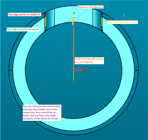
    Can you just measure the OD of the part,  the ID of the part, and take hits along the tab surfaces? Then construct lines, and create pierce/intersect points to that outer circle and then construct reverse lines with the first 2 lines you made originally, and create pierce/intersect points to that inner circle. THEN with pierce points you can construct midpoints so they will be in center of the slot walls. Then with those 2 midpoints create a midpoint. And then with that third midpoint you can create a line from the origin circle to it for rotation? Alternatively you can probably create 2 more lines with the 4 pierce points, then make a midline of those 2 lines

  • I will throw this method into the ring... It will be pretty close, and repeatable, definitely will want to repeat the same alignment a couple times to get it refined. 
    We had the advantage of having a vision system before we had a CMM, this is how we did it on the vision system and translated that experience to the CMM.

  • Dang, we both posted practically the same idea. What are the odds of that?

Reply Children
No Data