
hi team pls share the any one auto calibration program
Your Products have been synced, click here to refresh
hi team pls share the any one auto calibration program
look in your "C:\Users\Public\Documents\Hexagon\PC-DMIS\Examples" folder there is a hexagon provided example program.
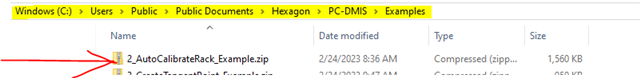
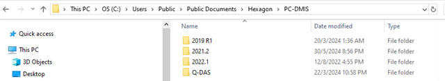
hi t.q for your replay . that folder not found in my pc . so please share calibration prg
PART NAME : AutoCalibrate_Tips_With_ProbeChanger
REV NUMBER : v1.0
SER NUMBER : 001
STATS COUNT : 1
STARTUP =ALIGNMENT/START,RECALL:USE_PART_SETUP,LIST=YES
ALIGNMENT/END
$$ NO,
==========================================================================================================
.
. Hexagon example measurement routine showing how to structure a measurement routine that
. auto-calibrates all probes in a tool changer rack.
.
. PLEASE NOTE: This example is for visual reference only and users should not attempt to execute it
. either on or offline. To avoid accidental execution a ROUTINE/END command has been inserted
. immediately after this comment.
.
==========================================================================================================
ROUTINE/END
$$ NO,
. 1) The prehit, retract, movespeed & touchspeed will have no effect on tha auto-calibrate commands
. since these values are set independently for each probe within the probe utilities window and
. form part of the parameter set information. However, it is good practice to include them in
. your program so long as care is taken to ensure they match the settings being used during
. probe calibration - especially if you are going to include any DCC moves or feature measurement
. as part of the auto-calibrate routine (for example any additional probe checks - see item 99)
.
. PLEASE NOTE: This example uses the pre-defined ALL-TIPS-WITH-DEFAULTS parameter set.
. However, it is worth noting that this will apply your default settings to every tip
. of every probefile and so it may not be suitable for users who wish to apply different
. settings to each probe or who want to calibrate the tips in a specific order.
.
. For information on creating specific parameter sets, please refer to the PC-Dmis help files.
.
MODE/DCC
PREHIT/2.5
RETRACT/2.5
MOVESPEED/ 250
TOUCHSPEED/ 5
FLY/ON
FORMAT/TEXT,OPTIONS, ,HEADINGS,SYMBOLS, ;NOM,TOL,MEAS,DEV,OUTTOL, ,
$$ NO,
.
. 2) First LOADPROBE command - Whenever you are using multiple probefiles within measurement routines
. you should designate a particular tip from a particular probefile as the "master".
. This would typically be tip1 (or A0/B0) of the probe stored in slot 1.
.
. The primary function of this "master" tip is to define the calibration sphere (TOOL) position.
. In order to avoid erroneaous offsets when using multiple probe files, it is best practice to ALWAYS calibrate
. the "master" tip first whenever your calibration shpere has moved.
. Ideally your "master" tip should be your shortest, most rigid stylus on your most simple "regular" probe build.
.
. In this example we use a Ø2x20mm M2 stylus on a HP_TMB_SF module.
.
. Another function for the "master" tip would be to calibrate any additional hardware such as a rotary table
. or probe changing rack. For this reason it makes sense that it should adhear to any specific requirements
. (where possible) for your particular make & model of probechanger. However this may not be practical if your
. probechanger requires a special, none standard stylus for it's calibration
. (some probechangers require a speciall cylindrical stylus for example, which should not be used for any other measurements).
.
. For more information see the embedded pdf below.
.
LOADPROBE/HP_TMB_SF_2X20
TIP/T1A0B0, SHANKIJK=0, 0, 1, ANGLE=0
LOADMACHINE/Global_S_5-7-5
$$ NO,
. 3) It is important to handle whether or not the calibration sphere has moved
. or if the CMM has been homed. This is because homing the machine resets
. the CMM co-ordinate system (alignment) and has the same effect as moving
. the calibration sphere - albeit by a very small amount. Failing to handle
. this properly is a common cause of error when using multiple probe files
. and can lead to incorrect tip offsets in your probefiles.
.
. In this example we use a YES/NO comment to prompt the operator to select
. whether the sphere has moved. Based on the answer, the MOVED variable
. is set to equal YES_MANUAL or NO and passed into the autocalibrate command
. in place of the explicit QUALTOOL_MOVED toggle value.
.
C1 =COMMENT/YESNO,NO,FULL SCREEN=YES,AUTO-CONTINUE=NO,OVC=NO,
Has the calibration sphere been moved
or has the CMM been homed since the
last time probes were calibrated?
.
If in doubt, choose YES
IF/C1.INPUT=="YES"
ASSIGN/MOVED="YES_MANUAL"
END_IF/
ELSE/
ASSIGN/MOVED="NO"
END_ELSE/
SLOT1 =LABEL/
ASSIGN/FAILED=""
AUTOCALIBRATE/PROBE, PARAMETER_SET=ALL-TIPS-WITH-DEFAULTS, QUALTOOL_MOVED=MOVED,
CHECK COLLISION=NO, SHOW_SUMMARY=YES, OVERWRITE_RESULTSFILE=NO
BEGIN AUTOCALIBRATE RESULTS FOR PROBE HP_TMB_SF_2X20 USING SET ALL-TIPS-WITH-DEFAULTS
Probe file=HP_TMB_SF_2X20 Date=02/08/2019 Time=11:25:28
Leitz_30mm_Sphere CENT X 199.305 Y 202.393 Z -401.301 D 30.000
T1A0B0 THEO X 0.000 Y 12.000 Z 180.675 D 2.000
T1A0B0 MEAS X 0.000 Y 12.000 Z 180.675 D 1.939 StdDev 0.004
T1A-30B90 THEO X 56.645 Y -0.000 Z 168.712 D 2.000
T1A-30B90 MEAS X 56.334 Y -0.485 Z 168.720 D 1.937 StdDev 0.004
T1A-90B0 THEO X 0.000 Y -134.075 Z 58.600 D 2.000
T1A-90B0 MEAS X -1.559 Y -133.747 Z 58.711 D 1.939 StdDev 0.003
T1A-90B90 THEO X 134.075 Y -0.000 Z 58.600 D 2.000
T1A-90B90 MEAS X 133.625 Y -1.194 Z 58.735 D 1.940 StdDev 0.003
END AUTOCALIBRATE RESULTS FOR PROBE HP_TMB_SF_2X20 USING SET ALL-TIPS-WITH-DEFAULTS
$$ NO,
. 4) Check the results.
.
. With the SHOW_SUMARY toggle set to YES, the calibration results will be
. displayed both in the edit window and on the report.
. However, this relies on the CMM user understanding and verifying those results.
.
. On shopfloor systems that may be manned by operators with little or no CMM experience
. it can be beneficial to programatically verify the calibration results and
. display a warning message should they fail.
.
. Here we use the PROBEDATA function to retrieve the probe offsets, tip diameter and standard deviation
.
. Standard deviation is a measure that is used to quantify the amount of variation or dispersion of a set of data values
. - in this case the points taken on the sphere by each tip during calibration. Therefore it is a good indicator of whether the
. calibration was "good" or "bad" since a large value could mean a bad point (or points). Typical examples of what could cause
. large standard deviation values might include dirt on the tip or calibration sphere, a damaged tip or calibration sphere,
. an incorrectly tightened tip or calibration sphere, the tip "shanking" due to incorrect settings.
.
. Tip diameter can help to identify damage, an incorrectly built probe or incorrect settings as it should not significantly differ from
. its nominal size. It is worth noting that for Analogue probing systems (HP-S-X1H, SP25 etc) the measured diameter will exactly match the nomiinal
. size and there will be an addition PRBDEV value (probe radius deviation) which should always be negative.
. For mechanical touch trigger probes such the HP-TMB or TP20, the measured diameter should always be smaller than it's nominal size - the
. amount of deviation will vary depending on how long / flexable the stylus is and the force level of the module being used. The longer the stylus
. or higher the module's trigger foce, the bigger the dviation will be.
.
. Tip offsets can be compared to the values obtained from their first calibration as, although the probe offests may differ from
. their nominal values due to the manfacuting accuracy of the components and the mechanical relationship of how the probe is mounted
. to the CMM, they should not vary significantly from run to run unless the probe build physically changes. Any change to the
. offsets might indicate a loose or damaged stylus or that it has been broken down and re-built.
. You may find it beneficiall to output the probe offset reults to a statistical package to enable easier tracking of variation.
. This can help in identifying a suitable calibration interval for example.
.
. It should be noted that whenever the autocalibrate command QUALTOOL_MOVED toggle is set to YES, or you select YES_MANUAL or YES_DCC
. when performing a probe calibration via the probe utilities window, the first tip calibrated will have zero probe offset
. - it's theo and measured X, Y & Z should be identical.
.
. Should the tests fail, a YES/NO comment provides the operator with a list of possible causes that they can attempt to rectify
. before choosing to repeat the calibration (by selecting YES) or move on to the next probe (by selecting NO).
.
WORKPLANE/ZPLUS
ASSIGN/V1=PROBEDATA("Toffset","T1A0B0")
ASSIGN/V2=PROBEDATA("offset","T1A0B0")
ASSIGN/V3=PROBEDATA("diam","T1A0B0")
ASSIGN/V4=PROBEDATA("standarddeviation","T1A0B0")
F1 =GENERIC/CYLINDER,DEPENDENT,CARTESIAN,OUT,$
NOM/XYZ,<V1.X,V1.Y,V1.Z>,$
MEAS/XYZ,<V2.X,V2.Y,V2.Z>,$
NOM/IJK,<0,0,1>,$
MEAS/IJK,<0,0,1>,$
DIAMETER/2,V3,$
DISTANCE/0,V4
DIM LOC1= LOCATION OF CYLINDER F1 UNITS=MM ,$
GRAPH=OFF TEXT=OFF MULT=10.00 OUTPUT=BOTH HALF ANGLE=NO
AX NOMINAL +TOL -TOL MEAS DEV OUTTOL
X 0.000 0.005 0.005 -0.080 -0.080 0.075 <--------
Y 12.000 0.005 0.005 11.854 -0.146 0.141 <--------
Z 198.175 0.005 0.005 198.210 0.035 0.030 -------->
D 2.000 0.250 0.250 3.960 1.960 1.710 -------->
L 0.000 0.010 0.050 0.003 0.003 0.000 -------#-
END OF DIMENSION LOC1
IF/(LOC1.D.OUTTOL<>0) OR (LOC1.L.OUTTOL<>0)
ASSIGN/FAILED=FAILED+"T1A0B0 , "
END_IF/
ASSIGN/V2=PROBEDATA("offset","T1A-30B90")
ASSIGN/V3=PROBEDATA("diam","T1A-30B90")
ASSIGN/V4=PROBEDATA("standarddeviation","T1A-30B90")
F2 =GENERIC/CYLINDER,DEPENDENT,CARTESIAN,OUT,$
NOM/XYZ,<56.332,-0.481,168.72>,$
MEAS/XYZ,<V2.X,V2.Y,V2.Z>,$
NOM/IJK,<0,0,1>,$
MEAS/IJK,<0,0,1>,$
DIAMETER/2,V3,$
DISTANCE/0,V4
DIM LOC2= LOCATION OF CYLINDER F2 UNITS=MM ,$
GRAPH=OFF TEXT=OFF MULT=10.00 OUTPUT=BOTH HALF ANGLE=NO
AX NOMINAL +TOL -TOL MEAS DEV OUTTOL
X 56.332 0.005 0.005 0.000 -56.332 56.327 <--------
Y -0.481 0.005 0.005 0.000 0.481 0.476 -------->
Z 168.720 0.005 0.005 0.000 -168.720 168.715 <--------
D 2.000 0.250 0.250 0.000 -2.000 1.750 <--------
L 0.000 0.010 0.050 0.000 0.000 0.000 -------#-
END OF DIMENSION LOC2
IF/(LOC2.D.OUTTOL<>0) OR (LOC2.L.OUTTOL<>0)
ASSIGN/FAILED=FAILED+"T1A-30B90 , "
END_IF/
ASSIGN/V2=PROBEDATA("offset","T1A-90B0")
ASSIGN/V3=PROBEDATA("diam","T1A-90B0")
ASSIGN/V4=PROBEDATA("standarddeviation","T1A-90B0")
F3 =GENERIC/CYLINDER,DEPENDENT,CARTESIAN,OUT,$
NOM/XYZ,<-1.56,-133.75,58.71>,$
MEAS/XYZ,<V2.X,V2.Y,V2.Z>,$
NOM/IJK,<0,0,1>,$
MEAS/IJK,<0,0,1>,$
DIAMETER/2,V3,$
DISTANCE/0,V4
DIM LOC3= LOCATION OF CYLINDER F3 UNITS=MM ,$
GRAPH=OFF TEXT=OFF MULT=10.00 OUTPUT=BOTH HALF ANGLE=NO
AX NOMINAL +TOL -TOL MEAS DEV OUTTOL
X -1.560 0.005 0.005 0.000 1.560 1.555 -------->
Y -133.750 0.005 0.005 0.000 133.750 133.745 -------->
Z 58.710 0.005 0.005 0.000 -58.710 58.705 <--------
D 2.000 0.250 0.250 0.000 -2.000 1.750 <--------
L 0.000 0.010 0.050 0.000 0.000 0.000 -------#-
END OF DIMENSION LOC3
IF/(LOC3.D.OUTTOL<>0) OR (LOC3.L.OUTTOL<>0)
ASSIGN/FAILED=FAILED+"T1A-30B0 , "
END_IF/
ASSIGN/V2=PROBEDATA("offset","T1A-90B90")
ASSIGN/V3=PROBEDATA("diam","T1A-90B90")
ASSIGN/V4=PROBEDATA("standarddeviation","T1A-90B90")
F4 =GENERIC/CYLINDER,DEPENDENT,CARTESIAN,OUT,$
NOM/XYZ,<133.625,-1.195,58.736>,$
MEAS/XYZ,<V2.X,V2.Y,V2.Z>,$
NOM/IJK,<0,0,1>,$
MEAS/IJK,<0,0,1>,$
DIAMETER/2,V3,$
DISTANCE/0,V4
DIM LOC4= LOCATION OF CYLINDER F4 UNITS=MM ,$
GRAPH=OFF TEXT=OFF MULT=10.00 OUTPUT=BOTH HALF ANGLE=NO
AX NOMINAL +TOL -TOL MEAS DEV OUTTOL
X 133.625 0.005 0.005 0.000 -133.625 133.620 <--------
Y -1.195 0.005 0.005 0.000 1.195 1.190 -------->
Z 58.736 0.005 0.005 0.000 -58.736 58.731 <--------
D 2.000 0.250 0.250 0.000 -2.000 1.750 <--------
L 0.000 0.010 0.050 0.000 0.000 0.000 -------#-
END OF DIMENSION LOC4
IF/(LOC6.D.OUTTOL<>0) OR (LOC6.L.OUTTOL<>0)
ASSIGN/FAILED=FAILED+"T1A-90B90"
END_IF/
IF/FAILED<>""
C2 =COMMENT/YESNO,NO,FULL SCREEN=YES,AUTO-CONTINUE=NO,OVC=NO,
. Probe Calibration failed for the following tips .
FAILED
Check probe builds are correct
Check probes & cal sphere are clean
Check probes & cal sphere are free from damage
Check probes & cal sphere are tightend correctly
Do you want to re-calibrate slot 1?
IF/C2.INPUT=="YES"
GOTO/SLOT1
END_IF/
END_IF/
$$ NO,
. 5) Second (and subsequent) LOADPROBE commands. The remaining probes can now be calibrated.
. It is VERY IMPORTANT that the QUALTOOL_MOVED toggle be set to NO for all AUTOCALIBRATE
. commands after this point or the association beteween probes will be lost.
. Also, the FAILED assignment must be reset to = "" or it will retain data from any previous probes that were checked.
.
LOADPROBE/HP_TMB_SF_2X40
TIP/T1A0B0, SHANKIJK=0, 0, 1, ANGLE=0
SLOT2 =LABEL/
ASSIGN/FAILED=""
AUTOCALIBRATE/PROBE, PARAMETER_SET=ALL-TIPS-WITH-DEFAULTS, QUALTOOL_MOVED=NO,
CHECK COLLISION=NO, SHOW_SUMMARY=YES, OVERWRITE_RESULTSFILE=NO
BEGIN AUTOCALIBRATE RESULTS FOR PROBE HP_TMB_SF_2X40 USING SET ALL-TIPS-WITH-DEFAULTS
Probe file=HP_TMB_SF_2X40 Date=02/08/2019 Time=11:46:08
T1A0B0 THEO X 0.000 Y 12.000 Z 200.675 D 2.000
T1A0B0 MEAS X 0.211 Y 11.956 Z 200.697 D 1.961 StdDev 0.002
T1A90B-90 THEO X 154.075 Y 0.000 Z 34.600 D 2.000
T1A90B-90 MEAS X 153.595 Y -1.750 Z 34.804 D 1.963 StdDev 0.001
T1A90B0 THEO X 0.000 Y 154.075 Z 34.600 D 2.000
T1A90B0 MEAS X 1.666 Y 153.954 Z 34.916 D 1.963 StdDev 0.002
T1A90B90 THEO X -154.075 Y 0.000 Z 34.600 D 2.000
T1A90B90 MEAS X -154.071 Y 2.015 Z 34.892 D 1.963 StdDev 0.002
T1A90B180 THEO X 0.000 Y -154.075 Z 34.600 D 2.000
T1A90B180 MEAS X -2.134 Y -153.701 Z 34.798 D 1.963 StdDev 0.002
END AUTOCALIBRATE RESULTS FOR PROBE HP_TMB_SF_2X40 USING SET ALL-TIPS-WITH-DEFAULTS
$$ NO,
. 6) The same method of checking results can be used for each probe as was used for slot 1.
. The only differences being the label name that the execution will jump back to
. should the test fail and, of course, the tip angles that are referenced for the checks.
. To make this example easy to follow, the labels have been named SLOT1, SLOT2, SLOT3 etc...
. so that they correspond with the rack location of the probes being calibrated.
.
ASSIGN/V2=PROBEDATA("offset","T1A0B0")
ASSIGN/V3=PROBEDATA("diam","T1A0B0")
ASSIGN/V4=PROBEDATA("standarddeviation","T1A0B0")
F5 =GENERIC/CYLINDER,DEPENDENT,CARTESIAN,OUT,$
NOM/XYZ,<0.215,11.96,200.7>,$
MEAS/XYZ,<V2.X,V2.Y,V2.Z>,$
NOM/IJK,<0,0,1>,$
MEAS/IJK,<0,0,1>,$
DIAMETER/2,V3,$
DISTANCE/0,V4
DIM LOC5= LOCATION OF CYLINDER F5 UNITS=MM ,$
GRAPH=OFF TEXT=OFF MULT=10.00 OUTPUT=BOTH HALF ANGLE=NO
AX NOMINAL +TOL -TOL MEAS DEV OUTTOL
X 0.215 0.005 0.005 0.211 -0.004 0.000 -#-------
Y 11.960 0.005 0.005 11.956 -0.004 0.000 #--------
Z 200.700 0.005 0.005 200.697 -0.003 0.000 --#------
D 2.000 0.250 0.250 1.961 -0.039 0.000 ---#-----
L 0.000 0.010 0.050 0.002 0.002 0.000 -------#-
END OF DIMENSION LOC5
IF/(LOC6.D.OUTTOL<>0) OR (LOC6.L.OUTTOL<>0)
ASSIGN/FAILED=FAILED+"T1A0B0 , "
END_IF/
ASSIGN/V2=PROBEDATA("offset","T1A90B-90")
ASSIGN/V3=PROBEDATA("diam","T1A90B-90")
ASSIGN/V4=PROBEDATA("standarddeviation","T1A90B-90")
F6 =GENERIC/CYLINDER,DEPENDENT,CARTESIAN,OUT,$
NOM/XYZ,<153.59,-1.75,34.8>,$
MEAS/XYZ,<V2.X,V2.Y,V2.Z>,$
NOM/IJK,<0,0,1>,$
MEAS/IJK,<0,0,1>,$
DIAMETER/2,V3,$
DISTANCE/0,V4
DIM LOC6= LOCATION OF CYLINDER F6 UNITS=MM ,$
GRAPH=OFF TEXT=OFF MULT=10.00 OUTPUT=BOTH HALF ANGLE=NO
AX NOMINAL +TOL -TOL MEAS DEV OUTTOL
X 153.590 0.005 0.005 153.595 0.005 0.000 --------#
Y -1.750 0.005 0.005 -1.750 0.000 0.000 ----#----
Z 34.800 0.005 0.005 34.804 0.004 0.000 -------#-
D 2.000 0.250 0.250 1.963 -0.037 0.000 ---#-----
L 0.000 0.010 0.050 0.001 0.001 0.000 -------#-
END OF DIMENSION LOC6
IF/(LOC6.D.OUTTOL<>0) OR (LOC6.L.OUTTOL<>0)
ASSIGN/FAILED=FAILED+"T1A90B-90 , "
END_IF/
ASSIGN/V2=PROBEDATA("offset","T1A90B0")
ASSIGN/V3=PROBEDATA("diam","T1A90B0")
ASSIGN/V4=PROBEDATA("standarddeviation","T1A90B0")
F7 =GENERIC/CYLINDER,DEPENDENT,CARTESIAN,OUT,$
NOM/XYZ,<1.67,153.95,34.92>,$
MEAS/XYZ,<V2.X,V2.Y,V2.Z>,$
NOM/IJK,<0,0,1>,$
MEAS/IJK,<0,0,1>,$
DIAMETER/2,V3,$
DISTANCE/0,V4
DIM LOC7= LOCATION OF CYLINDER F7 UNITS=MM ,$
GRAPH=OFF TEXT=OFF MULT=10.00 OUTPUT=BOTH HALF ANGLE=NO
AX NOMINAL +TOL -TOL MEAS DEV OUTTOL
X 1.670 0.005 0.005 1.666 -0.004 0.000 #--------
Y 153.950 0.005 0.005 153.954 0.004 0.000 --------#
Z 34.920 0.005 0.005 34.916 -0.004 0.000 #--------
D 2.000 0.250 0.250 1.963 -0.037 0.000 ---#-----
L 0.000 0.010 0.050 0.002 0.002 0.000 -------#-
END OF DIMENSION LOC7
IF/(LOC7.D.OUTTOL<>0) OR (LOC7.L.OUTTOL<>0)
ASSIGN/FAILED=FAILED+"T1A90B0 , "
END_IF/
ASSIGN/V2=PROBEDATA("offset","T1A90B90")
ASSIGN/V3=PROBEDATA("diam","T1A90B90")
ASSIGN/V4=PROBEDATA("standarddeviation","T1A90B90")
F8 =GENERIC/CYLINDER,DEPENDENT,CARTESIAN,OUT,$
NOM/XYZ,<-154.07,2.02,34.89>,$
MEAS/XYZ,<V2.X,V2.Y,V2.Z>,$
NOM/IJK,<0,0,1>,$
MEAS/IJK,<0,0,1>,$
DIAMETER/2,V3,$
DISTANCE/0,V4
DIM LOC8= LOCATION OF CYLINDER F8 UNITS=MM ,$
GRAPH=OFF TEXT=OFF MULT=10.00 OUTPUT=BOTH HALF ANGLE=NO
AX NOMINAL +TOL -TOL MEAS DEV OUTTOL
X -154.070 0.005 0.005 -154.071 -0.001 0.000 ---#-----
Y 2.020 0.005 0.005 2.015 -0.005 0.000 #--------
Z 34.890 0.005 0.005 34.892 0.002 0.000 ------#--
D 2.000 0.250 0.250 1.963 -0.037 0.000 ---#-----
L 0.000 0.010 0.050 0.002 0.002 0.000 -------#-
END OF DIMENSION LOC8
IF/(LOC8.D.OUTTOL<>0) OR (LOC8.L.OUTTOL<>0)
ASSIGN/FAILED=FAILED+"T1A90B90 , "
END_IF/
ASSIGN/V2=PROBEDATA("offset","T1A90B180")
ASSIGN/V3=PROBEDATA("diam","T1A90B180")
ASSIGN/V4=PROBEDATA("standarddeviation","T1A90B180")
F9 =GENERIC/CYLINDER,DEPENDENT,CARTESIAN,OUT,$
NOM/XYZ,<-2.13,-153.7,34.8>,$
MEAS/XYZ,<V2.X,V2.Y,V2.Z>,$
NOM/IJK,<0,0,1>,$
MEAS/IJK,<0,0,1>,$
DIAMETER/2,V3,$
DISTANCE/0,V4
DIM LOC9= LOCATION OF CYLINDER F9 UNITS=MM ,$
GRAPH=OFF TEXT=OFF MULT=10.00 OUTPUT=BOTH HALF ANGLE=NO
AX NOMINAL +TOL -TOL MEAS DEV OUTTOL
X -2.130 0.005 0.005 -2.134 -0.004 0.000 #--------
Y -153.700 0.005 0.005 -153.701 -0.001 0.000 ---#-----
Z 34.800 0.005 0.005 34.798 -0.002 0.000 ---#-----
D 2.000 0.250 0.250 1.963 -0.037 0.000 ---#-----
L 0.000 0.010 0.050 0.002 0.002 0.000 -------#-
END OF DIMENSION LOC9
IF/(LOC9.D.OUTTOL<>0) OR (LOC9.L.OUTTOL<>0)
ASSIGN/FAILED=FAILED+"T1A90B180"
END_IF/
IF/FAILED<>""
C2 =COMMENT/YESNO,NO,FULL SCREEN=YES,AUTO-CONTINUE=NO,OVC=NO,
. Probe Calibration failed for the following tips .
FAILED
Check probe builds are correct
Check probes & cal sphere are clean
Check probes & cal sphere are free from damage
Check probes & cal sphere are tightend correctly
Do you want to re-calibrate slot 2?
IF/C2.INPUT=="YES"
GOTO/SLOT2
END_IF/
END_IF/
LOADPROBE/HP_TMB_SF_3X30
TIP/T1A0B0, SHANKIJK=0, 0, 1, ANGLE=0
SLOT3 =LABEL/
ASSIGN/FAILED=""
AUTOCALIBRATE/PROBE, PARAMETER_SET=ALL-TIPS-WITH-DEFAULTS, QUALTOOL_MOVED=NO,
CHECK COLLISION=NO, SHOW_SUMMARY=YES, OVERWRITE_RESULTSFILE=NO
BEGIN AUTOCALIBRATE RESULTS FOR PROBE HP_TMB_SF_3X30 USING SET ALL-TIPS-WITH-DEFAULTS
Probe file=HP_TMB_SF_3X30 Date=02/08/2019 Time=11:58:44
T1A0B0 THEO X 0.000 Y 12.000 Z 190.675 D 3.000
T1A0B0 MEAS X -0.044 Y 12.223 Z 190.713 D 2.964 StdDev 0.002
T1A-45B-90 THEO X -93.391 Y -0.000 Z 156.962 D 3.000
T1A-45B-90 MEAS X -93.344 Y 1.092 Z 157.195 D 2.965 StdDev 0.001
T1A-90B-90 THEO X -144.075 Y -0.000 Z 58.600 D 3.000
T1A-90B-90 MEAS X -144.125 Y 1.576 Z 59.036 D 2.967 StdDev 0.002
T1A90B0 THEO X 0.000 Y 144.075 Z 34.600 D 3.000
T1A90B0 MEAS X 1.305 Y 143.974 Z 34.652 D 2.965 StdDev 0.001
END AUTOCALIBRATE RESULTS FOR PROBE HP_TMB_SF_3X30 USING SET ALL-TIPS-WITH-DEFAULTS
ASSIGN/V2=PROBEDATA("offset","T1A0B0")
ASSIGN/V3=PROBEDATA("diam","T1A0B0")
ASSIGN/V4=PROBEDATA("standarddeviation","T1A0B0")
F10 =GENERIC/CYLINDER,DEPENDENT,CARTESIAN,OUT,$
NOM/XYZ,<-0.04,12.22,190.71>,$
MEAS/XYZ,<V2.X,V2.Y,V2.Z>,$
NOM/IJK,<0,0,1>,$
MEAS/IJK,<0,0,1>,$
DIAMETER/3,V3,$
DISTANCE/0,V4
DIM LOC10= LOCATION OF CYLINDER F10 UNITS=MM ,$
GRAPH=OFF TEXT=OFF MULT=10.00 OUTPUT=BOTH HALF ANGLE=NO
AX NOMINAL +TOL -TOL MEAS DEV OUTTOL
X -0.040 0.005 0.005 -0.044 -0.004 0.000 -#-------
Y 12.220 0.005 0.005 12.223 0.003 0.000 -------#-
Z 190.710 0.005 0.005 190.713 0.003 0.000 -------#-
D 3.000 0.250 0.250 2.964 -0.036 0.000 ---#-----
L 0.000 0.010 0.050 0.002 0.002 0.000 -------#-
END OF DIMENSION LOC10
IF/(LOC10.D.OUTTOL<>0) OR (LOC10.L.OUTTOL<>0)
ASSIGN/FAILED=FAILED+"T1A0B0 , "
END_IF/
ASSIGN/V2=PROBEDATA("offset","T1A-45B-90")
ASSIGN/V3=PROBEDATA("diam","T1A-45B-90")
ASSIGN/V4=PROBEDATA("standarddeviation","T1A-45B-90")
F11 =GENERIC/CYLINDER,DEPENDENT,CARTESIAN,OUT,$
NOM/XYZ,<-93.34,1.09,157.2>,$
MEAS/XYZ,<V2.X,V2.Y,V2.Z>,$
NOM/IJK,<0,0,1>,$
MEAS/IJK,<0,0,1>,$
DIAMETER/3,V3,$
DISTANCE/0,V4
DIM LOC11= LOCATION OF CYLINDER F11 UNITS=MM ,$
GRAPH=OFF TEXT=OFF MULT=10.00 OUTPUT=BOTH HALF ANGLE=NO
AX NOMINAL +TOL -TOL MEAS DEV OUTTOL
X -93.340 0.005 0.005 -93.344 -0.004 0.000 -#-------
Y 1.090 0.005 0.005 1.092 0.002 0.000 ------#--
Z 157.200 0.005 0.005 157.195 -0.005 0.000 #--------
D 3.000 0.250 0.250 2.965 -0.035 0.000 ---#-----
L 0.000 0.010 0.050 0.001 0.001 0.000 -------#-
END OF DIMENSION LOC11
IF/(LOC11.D.OUTTOL<>0) OR (LOC11.L.OUTTOL<>0)
ASSIGN/FAILED=FAILED+"T1A-45B-90 , "
END_IF/
ASSIGN/V2=PROBEDATA("offset","T1A-90B-90")
ASSIGN/V3=PROBEDATA("diam","T1A-90B-90")
ASSIGN/V4=PROBEDATA("standarddeviation","T1A-90B-90")
F12 =GENERIC/CYLINDER,DEPENDENT,CARTESIAN,OUT,$
NOM/XYZ,<-144.125,1.575,59.04>,$
MEAS/XYZ,<V2.X,V2.Y,V2.Z>,$
NOM/IJK,<0,0,1>,$
MEAS/IJK,<0,0,1>,$
DIAMETER/3,V3,$
DISTANCE/0,V4
DIM LOC12= LOCATION OF CYLINDER F12 UNITS=MM ,$
GRAPH=OFF TEXT=OFF MULT=10.00 OUTPUT=BOTH HALF ANGLE=NO
AX NOMINAL +TOL -TOL MEAS DEV OUTTOL
X -144.125 0.005 0.005 -144.125 0.000 0.000 ----#----
Y 1.575 0.005 0.005 1.576 0.001 0.000 -----#---
Z 59.040 0.005 0.005 59.036 -0.004 0.000 #--------
D 3.000 0.250 0.250 2.967 -0.033 0.000 ---#-----
L 0.000 0.010 0.050 0.002 0.002 0.000 -------#-
END OF DIMENSION LOC12
IF/(LOC12.D.OUTTOL<>0) OR (LOC12.L.OUTTOL<>0)
ASSIGN/FAILED=FAILED+"T1A-90B-90 , "
END_IF/
ASSIGN/V2=PROBEDATA("offset","T1A90B0")
ASSIGN/V3=PROBEDATA("diam","T1A90B0")
ASSIGN/V4=PROBEDATA("standarddeviation","T1A90B0")
F13 =GENERIC/CYLINDER,DEPENDENT,CARTESIAN,OUT,$
NOM/XYZ,<1.3,143.975,34.65>,$
MEAS/XYZ,<V2.X,V2.Y,V2.Z>,$
NOM/IJK,<0,0,1>,$
MEAS/IJK,<0,0,1>,$
DIAMETER/3,V3,$
DISTANCE/0,V4
DIM LOC13= LOCATION OF CYLINDER F13 UNITS=MM ,$
GRAPH=OFF TEXT=OFF MULT=10.00 OUTPUT=BOTH HALF ANGLE=NO
AX NOMINAL +TOL -TOL MEAS DEV OUTTOL
X 1.300 0.005 0.005 1.305 0.005 0.000 --------#
Y 143.975 0.005 0.005 143.974 -0.001 0.000 ---#-----
Z 34.650 0.005 0.005 34.652 0.002 0.000 ------#--
D 3.000 0.250 0.250 2.965 -0.035 0.000 ---#-----
L 0.000 0.010 0.050 0.001 0.001 0.000 -------#-
END OF DIMENSION LOC13
IF/(LOC13.D.OUTTOL<>0) OR (LOC13.L.OUTTOL<>0)
ASSIGN/FAILED=FAILED+"T1A90B0"
END_IF/
IF/FAILED<>""
C2 =COMMENT/YESNO,NO,FULL SCREEN=YES,AUTO-CONTINUE=NO,OVC=NO,
. Probe Calibration failed for the following tips .
FAILED
Check probe builds are correct
Check probes & cal sphere are clean
Check probes & cal sphere are free from damage
Check probes & cal sphere are tightend correctly
Do you want to re-calibrate slot 3?
IF/C2.INPUT=="YES"
GOTO/SLOT3
END_IF/
END_IF/
LOADPROBE/HP_TMB_SF_5WAYSTAR
TIP/T1A0B0, SHANKIJK=0, 0, 1, ANGLE=0
SLOT4 =LABEL/
ASSIGN/FAILED=""
AUTOCALIBRATE/PROBE, PARAMETER_SET=ALL-TIPS-WITH-DEFAULTS, QUALTOOL_MOVED=NO,
CHECK COLLISION=NO, SHOW_SUMMARY=YES, OVERWRITE_RESULTSFILE=NO
BEGIN AUTOCALIBRATE RESULTS FOR PROBE HP_TMB_SF_5WAYSTAR USING SET ALL-TIPS-WITH-DEFAULTS
Probe file=HP_TMB_SF_5WAYSTAR Date=02/08/2019 Time=12:12:01
T1A0B0 THEO X 0.000 Y 12.000 Z 198.175 D 4.000
T1A0B0 MEAS X -0.080 Y 11.854 Z 198.210 D 3.960 StdDev 0.003
T2A0B0 THEO X -23.500 Y 12.000 Z 172.175 D 2.000
T2A0B0 MEAS X -23.409 Y 14.200 Z 172.230 D 1.956 StdDev 0.004
T3A0B0 THEO X 0.000 Y -11.500 Z 172.175 D 2.000
T3A0B0 MEAS X -2.047 Y -11.349 Z 171.931 D 1.942 StdDev 0.007
T4A0B0 THEO X 23.500 Y 12.000 Z 172.175 D 2.000
T4A0B0 MEAS X 23.568 Y 10.055 Z 172.053 D 1.962 StdDev 0.003
T5A0B0 THEO X 0.000 Y 35.500 Z 172.175 D 2.000
T5A0B0 MEAS X 2.322 Y 35.589 Z 172.191 D 1.714 StdDev 0.025
Standard deviations for probe calibration exceed limit.
T5A0B0
Measured probe diameter error exceeds the limits.
T5A0B0
END AUTOCALIBRATE RESULTS FOR PROBE HP_TMB_SF_5WAYSTAR USING SET ALL-TIPS-WITH-DEFAULTS
ASSIGN/V2=PROBEDATA("offset","T1A0B0")
ASSIGN/V3=PROBEDATA("diam","T1A0B0")
ASSIGN/V4=PROBEDATA("standarddeviation","T1A0B0")
F14 =GENERIC/CYLINDER,DEPENDENT,CARTESIAN,OUT,$
NOM/XYZ,<-0.078,11.85,198.212>,$
MEAS/XYZ,<V2.X,V2.Y,V2.Z>,$
NOM/IJK,<0,0,1>,$
MEAS/IJK,<0,0,1>,$
DIAMETER/4,V3,$
DISTANCE/0,V4
DIM LOC14= LOCATION OF CYLINDER F14 UNITS=MM ,$
GRAPH=OFF TEXT=OFF MULT=10.00 OUTPUT=BOTH HALF ANGLE=NO
AX NOMINAL +TOL -TOL MEAS DEV OUTTOL
X -0.078 0.005 0.005 -0.080 -0.002 0.000 --#------
Y 11.850 0.005 0.005 11.854 0.004 0.000 -------#-
Z 198.212 0.005 0.005 198.210 -0.002 0.000 --#------
D 4.000 0.250 0.250 3.960 -0.040 0.000 ---#-----
L 0.000 0.010 0.050 0.003 0.003 0.000 -------#-
END OF DIMENSION LOC14
IF/(LOC14.D.OUTTOL<>0) OR (LOC14.L.OUTTOL<>0)
ASSIGN/FAILED=FAILED+"T1A0B0 , "
END_IF/
ASSIGN/V2=PROBEDATA("offset","T2A0B0")
ASSIGN/V3=PROBEDATA("diam","T2A0B0")
ASSIGN/V4=PROBEDATA("standarddeviation","T2A0B0")
F15 =GENERIC/CYLINDER,DEPENDENT,CARTESIAN,OUT,$
NOM/XYZ,<-23.41,14.2,172.23>,$
MEAS/XYZ,<V2.X,V2.Y,V2.Z>,$
NOM/IJK,<0,0,1>,$
MEAS/IJK,<0,0,1>,$
DIAMETER/2,V3,$
DISTANCE/0,V4
DIM LOC15= LOCATION OF CYLINDER F15 UNITS=MM ,$
GRAPH=OFF TEXT=OFF MULT=10.00 OUTPUT=BOTH HALF ANGLE=NO
AX NOMINAL +TOL -TOL MEAS DEV OUTTOL
X -23.410 0.005 0.005 -23.409 0.001 0.000 -----#---
Y 14.200 0.005 0.005 14.200 0.000 0.000 ----#----
Z 172.230 0.005 0.005 172.230 0.000 0.000 ----#----
D 2.000 0.250 0.250 1.956 -0.044 0.000 ---#-----
L 0.000 0.010 0.050 0.004 0.004 0.000 --------#
END OF DIMENSION LOC15
IF/(LOC15.D.OUTTOL<>0) OR (LOC15.L.OUTTOL<>0)
ASSIGN/FAILED=FAILED+"T2A0B0 , "
END_IF/
ASSIGN/V2=PROBEDATA("offset","T3A0B0")
ASSIGN/V3=PROBEDATA("diam","T3A0B0")
ASSIGN/V4=PROBEDATA("standarddeviation","T3A0B0")
F16 =GENERIC/CYLINDER,DEPENDENT,CARTESIAN,OUT,$
NOM/XYZ,<-2.05,-11.35,171.93>,$
MEAS/XYZ,<V2.X,V2.Y,V2.Z>,$
NOM/IJK,<0,0,1>,$
MEAS/IJK,<0,0,1>,$
DIAMETER/2,V3,$
DISTANCE/0,V4
DIM LOC16= LOCATION OF CYLINDER F16 UNITS=MM ,$
GRAPH=OFF TEXT=OFF MULT=10.00 OUTPUT=BOTH HALF ANGLE=NO
AX NOMINAL +TOL -TOL MEAS DEV OUTTOL
X -2.050 0.005 0.005 -2.047 0.003 0.000 ------#--
Y -11.350 0.005 0.005 -11.349 0.001 0.000 -----#---
Z 171.930 0.005 0.005 171.931 0.001 0.000 -----#---
D 2.000 0.250 0.250 1.942 -0.058 0.000 ---#-----
L 0.000 0.010 0.050 0.007 0.007 0.000 --------#
END OF DIMENSION LOC16
IF/(LOC16.D.OUTTOL<>0) OR (LOC16.L.OUTTOL<>0)
ASSIGN/FAILED=FAILED+"T3A0B0 , "
END_IF/
ASSIGN/V2=PROBEDATA("offset","T4A0B0")
ASSIGN/V3=PROBEDATA("diam","T4A0B0")
ASSIGN/V4=PROBEDATA("standarddeviation","T4A0B0")
F17 =GENERIC/CYLINDER,DEPENDENT,CARTESIAN,OUT,$
NOM/XYZ,<23.57,10.06,172.05>,$
MEAS/XYZ,<V2.X,V2.Y,V2.Z>,$
NOM/IJK,<0,0,1>,$
MEAS/IJK,<0,0,1>,$
DIAMETER/2,V3,$
DISTANCE/0,V4
DIM LOC17= LOCATION OF CYLINDER F17 UNITS=MM ,$
GRAPH=OFF TEXT=OFF MULT=10.00 OUTPUT=BOTH HALF ANGLE=NO
AX NOMINAL +TOL -TOL MEAS DEV OUTTOL
X 23.570 0.005 0.005 23.568 -0.002 0.000 --#------
Y 10.060 0.005 0.005 10.055 -0.005 0.000 #--------
Z 172.050 0.005 0.005 172.053 0.003 0.000 -------#-
D 2.000 0.250 0.250 1.962 -0.038 0.000 ---#-----
L 0.000 0.010 0.050 0.003 0.003 0.000 -------#-
END OF DIMENSION LOC17
IF/(LOC17.D.OUTTOL<>0) OR (LOC17.L.OUTTOL<>0)
ASSIGN/FAILED=FAILED+"T4A0B0 , "
END_IF/
ASSIGN/V2=PROBEDATA("offset","T5A0B0")
ASSIGN/V3=PROBEDATA("diam","T5A0B0")
ASSIGN/V4=PROBEDATA("standarddeviation","T5A0B0")
F18 =GENERIC/CYLINDER,DEPENDENT,CARTESIAN,OUT,$
NOM/XYZ,<2.32,35.59,172.19>,$
MEAS/XYZ,<V2.X,V2.Y,V2.Z>,$
NOM/IJK,<0,0,1>,$
MEAS/IJK,<0,0,1>,$
DIAMETER/2,V3,$
DISTANCE/0,V4
DIM LOC18= LOCATION OF CYLINDER F18 UNITS=MM ,$
GRAPH=OFF TEXT=OFF MULT=10.00 OUTPUT=BOTH HALF ANGLE=NO
AX NOMINAL +TOL -TOL MEAS DEV OUTTOL
X 2.320 0.005 0.005 2.322 0.002 0.000 ------#--
Y 35.590 0.005 0.005 35.589 -0.001 0.000 ---#-----
Z 172.190 0.005 0.005 172.191 0.001 0.000 -----#---
D 2.000 0.250 0.250 1.714 -0.286 0.036 <--------
L 0.000 0.010 0.050 0.025 0.025 0.015 -------->
END OF DIMENSION LOC18
IF/(LOC18.D.OUTTOL<>0) OR (LOC18.L.OUTTOL<>0)
ASSIGN/FAILED=FAILED+"T5A0B0 , "
END_IF/
IF/FAILED<>""
C2 =COMMENT/YESNO,NO,FULL SCREEN=YES,AUTO-CONTINUE=NO,OVC=NO,
. Probe Calibration failed for the following tips .
FAILED
Check probe builds are correct
Check probes & cal sphere are clean
Check probes & cal sphere are free from damage
Check probes & cal sphere are tightend correctly
Do you want to re-calibrate slot 4?
IF/C2.INPUT=="YES"
GOTO/SLOT4
DISPLAY/METAFILE, "", TO FIT, GOOD
END_IF/
END_IF/
A1 =ALIGNMENT/START,RECALL:STARTUP,LIST=YES
ALIGNMENT/TRANS_OFFSET,ZAXIS,-3000
ALIGNMENT/ENDI tried to attach the zipped folder but forum wont allow that. also you can use "parameter sets" for each probe and all tip angles used in each program. here is an example of what we have set.
SPH        =COMMENT/YESNO,NO,FULL SCREEN=NO,AUTO-CONTINUE=NO,OVC=NO,
            has the sphere moved?
            IF_GOTO/SPH.INPUT=="NO",GOTO = NOMOVE
            LOADPROBE/SERVICE
            TIP/T1A0B0, SHANKIJK=0, 0, 1, ANGLE=0
            AUTOCALIBRATE/PROBE, PARAMETER_SET=Master_A0B0, QUALTOOL_MOVED=YES_MANUAL,
                          CHECK COLLISION=NO, SHOW_SUMMARY=NO, OVERWRITE_RESULTSFILE=YES
NOMOVE     =LABEL/
            LOADPROBE/03X60
            TIP/T1A0B0, SHANKIJK=0, 0, 1, ANGLE=0
            AUTOCALIBRATE/PROBE, PARAMETER_SET=CALIBRATION_03X60, QUALTOOL_MOVED=NO,
                          CHECK COLLISION=NO, SHOW_SUMMARY=YES, OVERWRITE_RESULTSFILE=YES
BEGIN AUTOCALIBRATE RESULTS FOR PROBE 03X60 USING SET CALIBRATION_03X60
END AUTOCALIBRATE RESULTS FOR PROBE 03X60 USING SET CALIBRATION_03X60
            LOADPROBE/05X70
            TIP/T1A0B0, SHANKIJK=0, 0, 1, ANGLE=0
            AUTOCALIBRATE/PROBE, PARAMETER_SET=CALIBRATION_05X70, QUALTOOL_MOVED=NO,
                          CHECK COLLISION=NO, SHOW_SUMMARY=YES, OVERWRITE_RESULTSFILE=YES
BEGIN AUTOCALIBRATE RESULTS FOR PROBE 05X70 USING SET CALIBRATION_05X70
Probe file=05X70    Date=8/29/2022    Time=5:19:59 AM
Check Collision Disabled
T1A0B0         THEO X    0.000 Y    0.000 Z  294.000 D  0.500
T1A0B0         FAST X    0.488 Y   -0.176 Z  293.975 D  0.500 PrbRdv -0.002
T1A0B0         MEAS X    0.488 Y   -0.176 Z  293.974 D  0.500 PrbRdv -0.000 StdDev  0.000
END AUTOCALIBRATE RESULTS FOR PROBE 05X70 USING SET CALIBRATION_05X70
that folder not found in my pc . so please share calibration prg
You can download the examples from the PC-DMIS Homepage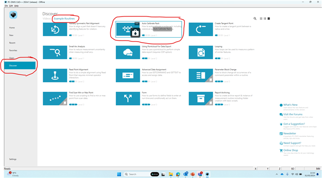
that folder not found in my pc . so please share calibration prg
You can download the examples from the PC-DMIS Homepage

t.q very much for all
| © 2025 Hexagon AB and/or its subsidiaries. | Privacy Policy | Cloud Services Agreement |

