hexagon logo

measuring 2d profile and straightness

 Hello all

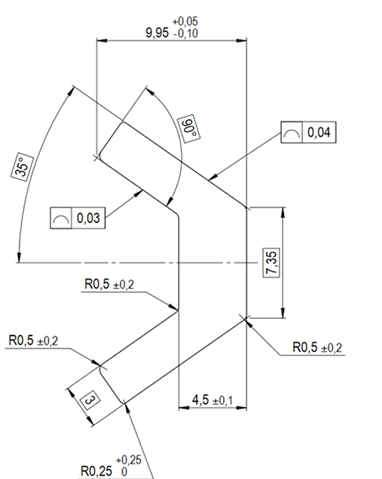
i have these profile bars (about 2.2meters long), and this is how the profile looks.
It also has a straightness callout along the entire length


I need to measure em and i know how to measure profile, i basicailly just do a bunch of vectorpoints, construct a scan set and evaluate profile.
For the straightness i guess i just measure a line across the entire lenght and evaluate straightness

But i dont really know how  to align the part. Ive taken a primary plane on the end face of the bar and then measure a line and offset angle 35.
But the ends of the bar are cut raw, and they re not really good feature to use for alignment.


How would i go about to align this part to evalute the staightness n profile?

TY ALL <3 

Parents
  • Profile of a line and straightness both apply to "any cross-section".  This means you should measure multiple, linear cross-sections across the entire extent of the part - not just a single line for straightness and a single cross-section for the profile.  You should evaluate each line and each cross-section individually.  The pass/fail decisions are based on the worst profile value amongst all the cross-sections and the worst straightness value amongst all the lines.  If you don't have scanning capability and are, instead, using individual vector points, you can probably cover the entire part in a grid of points and then construct lines running down the length of the part for the straightness and sets for the profile.

    Since there are no datums referenced, you can just do a 3D best-fit to all of your points for the alignment - pick all of the cross-sections (sets) and all of the lines from the 3D-Best-fit feature list and choose vector min/max as the fit type.

  • OK, ty!
    So BF alignment to ALL points or 
    Only select points in one cross section and BF align to em, then evalute profile for that cross section.

    and then continue to the next cross section?

Reply Children
  • 3D-Best-fit to all of the points.  If you are using legacy dimensioning, make sure you select "form only" for each of the profiles and select the vector min/max fit - make sure you are reporting the max and min deviation.  If you are using Geometric tolerance commands, just build the feature control frames.

  • thank you very much Neil. you ve always helped me, since the old PC-Dmis forum.

    Bonus Quest , theres also a "twist" specification for the part. How could I measure how much it twist?

  • I'm not sure about that one.  Maybe you could create a single set from all of the points and look at profile of a surface (instead of individual profile of a lines). If you turn on graphical analysis, that would allow you visually see any twist. 

    Or...

    If you need an actual number to report, you could compare the angular orientation of each cross-section.  You could maybe do a 2D best-fit, rotation only for each cross-section and assign the rotation values to variables.  You could then report the worst rotation value.

    Something like this...

    SCN1       =FEAT/SET,CARTESIAN
                THEO/<101.48431,16.204823,-8.260851>,<0,-1,0>
                ACTL/<101.534149,16.210164,-8.205152>,<0,-1,0>
                CONSTR/SET,BASIC,SCN_UV.HIT[5..5],SCN_UV.HIT[4..4],SCN_UV.HIT[3..3],SCN_UV.HIT[2..2],SCN_UV,,
    A4         =ALIGNMENT/START,RECALL:A3_DCC3,LIST=YES
                  ALIGNMENT/BF2D,XPLUS,VECTOR_MIN_MAX,CREATE WEIGHTS=NO,ROTONLY,0,0,0,0.167814
                  ITERATEANDREPIERCECAD=NO
                  Deviation Threshold=0,Pause Execution=NO
                  SHOWALLINPUTS=YES,SHOWALLPARAMS=NO
                    ID=SCN1
                    ID=
                ALIGNMENT/END
                IF/GETTEXT(149,0,GETCOMMAND(13,"UP",1))>180
                  ASSIGN/V5[1]=360-GETTEXT(149,0,GETCOMMAND(13,"UP",1))
                END_IF/
                ELSE/
                  ASSIGN/V5[1]=GETTEXT(149,0,GETCOMMAND(13,"UP",1))
                END_ELSE/
                RECALL/ALIGNMENT,INTERNAL,A3_DCC3
    SCN10      =FEAT/SET,CARTESIAN
                THEO/<93.84674,16.513116,-3.520193>,<0,-1,0>
                ACTL/<93.854699,16.517045,-3.528535>,<0,-1,0>
                CONSTR/SET,BASIC,CWS_UV.HIT[7..13],,
    A5         =ALIGNMENT/START,RECALL:A3_DCC3,LIST=YES
                  ALIGNMENT/BF2D,XPLUS,VECTOR_MIN_MAX,CREATE WEIGHTS=NO,ROTONLY,0,0,0,359.973278
                  ITERATEANDREPIERCECAD=NO
                  Deviation Threshold=0,Pause Execution=NO
                  SHOWALLINPUTS=YES,SHOWALLPARAMS=NO
                    ID=SCN10
                    ID=
                ALIGNMENT/END
                IF/GETTEXT(149,0,GETCOMMAND(13,"UP",1))>180
                  ASSIGN/V5[2]=360-GETTEXT(149,0,GETCOMMAND(13,"UP",1))
                END_IF/
                ELSE/
                  ASSIGN/V5[2]=GETTEXT(149,0,GETCOMMAND(13,"UP",1))
                END_ELSE/
                ASSIGN/V6=MAX(V5)
                RECALL/ALIGNMENT,INTERNAL,A3_DCC3
                COMMENT/REPT,
                "Twist values = "
                V5
                " "
                "Worst twist = " + V6

  • I know this is just an example, and a frame of reference. But does the SCN1 Constructed set have a small typo? It's using Hits 2 through 5, and then the whole scan

  • Just careless clicking + the example is just to illustrate the approach.  Basically, create a set for a cross-section, then use the 2D Best-fit (no translation) alignment to determine the rotational transformation from nominal.  Repeat the process for each cross-section, then find the worst rotational transformation to determine how much "twist" there is.