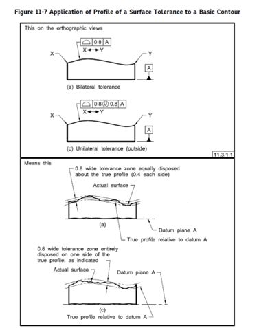
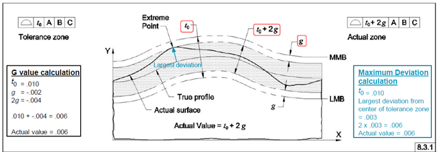
This is a little more of a GD&T standards question as opposed to a PC-DMIS question-- and probably a rudimentary question at that: According to ASME Y14.5.1 2019, to report out a profile, you take the extreme point on whatever side of the true profile it is, and double it to get the "actual zone." This is how profile is to be reported whether we're checking the profile manually with an indicator or using inspection software. My question is why is this the way to calculate it as opposed to adding the highs and lows together (FIM) like a form or orientation inspection? Engineers have asked me about this before and the most elementary way of answering it was to tell them that the profile result was representing what the profile tolerance "would have to be" in order to pass because doubling that value created a new zone (actual MMB and actual LMB). I'm still not entirely sure why.
For the record, I never read the actual ASME Y14.5.1 2019 text; I only watched videos about it so there's a good chance that I'm missing info.


