hexagon logo

Radius/ Arc Round Slot

Good morning,

I am new to PC-DMIS and CMM's in general so any tips and information would be greatly appreciated.

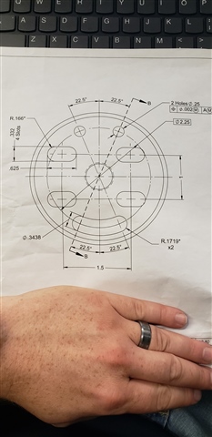
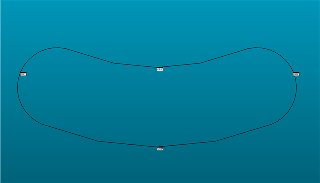
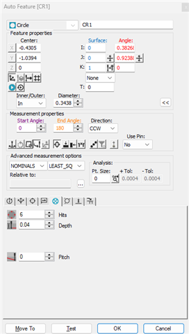
My current issue is trying to program this round slot on an arc.

I will attach a portion of the print, also I don't have a CAD model just part and print.

Thanks to all who help out with this.

Parents
  • I'm assuming your origin is in the center, as shown, the +X-axis is pointing to the right, and the +Y-axis is pointing up.

    The left slot R.1719 radius will have a center at (x, y, z) = (-1.125*cos(67.5°), -1.125*sin(67.5°), 0) ≈ (-0.4305, -1.0394, 0). Use an angle vector of <i, j, k> = <cos(67.5°), sin(67.5°), 0> ≈ <0.38268, 0.92388, 0>. Start angle = 0. End angle = 180. Measure CCW. The start and end angles can be offset (inward) slightly to avoid hitting the tangent point.

    The right slot R.1719 radius will have a center at (x, y, z) = (1.125*cos(67.5°), -1.125*sin(67.5°), 0) ≈ (0.4305, -1.0394, 0). Use an angle vector of <i, j, k> = <cos(67.5°), -sin(67.5°), 0> ≈ <0.38268, -0.92388, 0>. Start angle = 0. End angle = 180. Measure CCW. The start and end angles can be offset (inward) slightly to avoid hitting the tangent point.

    The inner R.9531 radius will have a center at (x, y, z) = (0, 0, 0). Use an angle vector of <i, j, k> = <-cos(67.5°), -sin(67.5°), 0> ≈ <-0.38268, -0.92388, 0>. Start angle = 0. End angle = 45°. Measure CCW.

    The outer R1.2969 radius will have a center at (x, y, z) = (0, 0, 0). Use an angle vector of <i, j, k> = <-cos(67.5°), -sin(67.5°), 0> ≈ <-0.38268, -0.92388, 0>. Start angle = 0. End angle = 45°. Measure CCW.

Reply
  • I'm assuming your origin is in the center, as shown, the +X-axis is pointing to the right, and the +Y-axis is pointing up.

    The left slot R.1719 radius will have a center at (x, y, z) = (-1.125*cos(67.5°), -1.125*sin(67.5°), 0) ≈ (-0.4305, -1.0394, 0). Use an angle vector of <i, j, k> = <cos(67.5°), sin(67.5°), 0> ≈ <0.38268, 0.92388, 0>. Start angle = 0. End angle = 180. Measure CCW. The start and end angles can be offset (inward) slightly to avoid hitting the tangent point.

    The right slot R.1719 radius will have a center at (x, y, z) = (1.125*cos(67.5°), -1.125*sin(67.5°), 0) ≈ (0.4305, -1.0394, 0). Use an angle vector of <i, j, k> = <cos(67.5°), -sin(67.5°), 0> ≈ <0.38268, -0.92388, 0>. Start angle = 0. End angle = 180. Measure CCW. The start and end angles can be offset (inward) slightly to avoid hitting the tangent point.

    The inner R.9531 radius will have a center at (x, y, z) = (0, 0, 0). Use an angle vector of <i, j, k> = <-cos(67.5°), -sin(67.5°), 0> ≈ <-0.38268, -0.92388, 0>. Start angle = 0. End angle = 45°. Measure CCW.

    The outer R1.2969 radius will have a center at (x, y, z) = (0, 0, 0). Use an angle vector of <i, j, k> = <-cos(67.5°), -sin(67.5°), 0> ≈ <-0.38268, -0.92388, 0>. Start angle = 0. End angle = 45°. Measure CCW.

Children
  • Thank you for this information but honestly, I am unsure what to do with it. 

    Basically, what I've been doing is taking hits and letting the measure feature do its thing.

    Along with using auto features for holes, counterbores, etc.

    I tried to just measure it using hits and it turns it into a straight round slot.

    I apologize for the lack of knowledge; I also thank you for the reply. 

  • You would put these XYZ and angle values into a circle auto feature.

    Insert > Feature > Auto > Circle

    CCW is counterclockwise measurement path

    As Jacob said, first 2 circles start and end angles can be offset inward to avoid hitting the tangent points

    For these 2 circles, increase start angle, decrease end angle to move them inward. You can play around and see what feels right

    CR1        =FEAT/CONTACT/CIRCLE/DEFAULT,CARTESIAN,IN,LEAST_SQR
                THEO/<-0.4305,-1.0394,0>,<0,0,1>,0.3438
                ACTL/<-0.4305,-1.0394,0>,<0,0,1>,0.3438
                TARG/<-0.4305,-1.0394,0>,<0,0,1>
                START ANG=0,END ANG=180
                ANGLE VEC=<0.3826803,0.9238808,0>
                DIRECTION=CCW
                SHOW FEATURE PARAMETERS=NO
                SHOW CONTACT PARAMETERS=NO
    CR2        =FEAT/CONTACT/CIRCLE/DEFAULT,CARTESIAN,IN,LEAST_SQR
                THEO/<0.4305,-1.0394,0>,<0,0,1>,0.3438
                ACTL/<0.4305,-1.0394,0>,<0,0,1>,0.3438
                TARG/<0.4305,-1.0394,0>,<0,0,1>
                START ANG=0,END ANG=180
                ANGLE VEC=<0.3826803,-0.9238808,0>
                DIRECTION=CCW
                SHOW FEATURE PARAMETERS=NO
                SHOW CONTACT PARAMETERS=NO
    CR3        =FEAT/CONTACT/CIRCLE/DEFAULT,CARTESIAN,IN,LEAST_SQR
                THEO/<0,0,0>,<0,0,1>,1.9062
                ACTL/<0,0,0>,<0,0,1>,1.9062
                TARG/<0,0,0>,<0,0,1>
                START ANG=0,END ANG=45
                ANGLE VEC=<-0.3826803,-0.9238808,0>
                DIRECTION=CCW
                SHOW FEATURE PARAMETERS=NO
                SHOW CONTACT PARAMETERS=NO
    CR4        =FEAT/CONTACT/CIRCLE/DEFAULT,CARTESIAN,IN,LEAST_SQR
                THEO/<0,0,0>,<0,0,1>,2.5938
                ACTL/<0,0,0>,<0,0,1>,2.5938
                TARG/<0,0,0>,<0,0,1>
                START ANG=0,END ANG=45
                ANGLE VEC=<-0.3826803,-0.9238808,0>
                DIRECTION=CCW
                SHOW FEATURE PARAMETERS=NO
                SHOW CONTACT PARAMETERS=NO

  • Thank you for that, I now understand what I need to do.

    I will give this a go and report back as time allows.

    I appreciate everyone who chipped in to help! 

  • Do note, as Jacob said. This is assuming that the origin is at the center of the round slot, you'll need to manually align to that first if you haven't already. Or at the very least use a read point, with a readpoint alignment and place your probe in the center of that round slot as best as you can before executing one of the circles. This tells the machine where the part is relative to the probe tip

    READ       =FEAT/POINT,CARTESIAN
                THEO/<0,0,0>,<0,0,1>
                ACTL/<0,0,0>,<0,0,1>
                READPOINT/
    READ_ALN   =ALIGNMENT/START,RECALL:STARTUP,LIST=YES
                  ALIGNMENT/TRANS,XAXIS,READ
                  ALIGNMENT/TRANS,YAXIS,READ
                  ALIGNMENT/TRANS,ZAXIS,READ
                ALIGNMENT/END

    Type read in the Edit window to generate a read point and change the theo/actual XYZ to 0,0,0 and the appropriate vector(IJK) to 0,0,1 if in Z+ for example