hexagon logo

Profile of surface

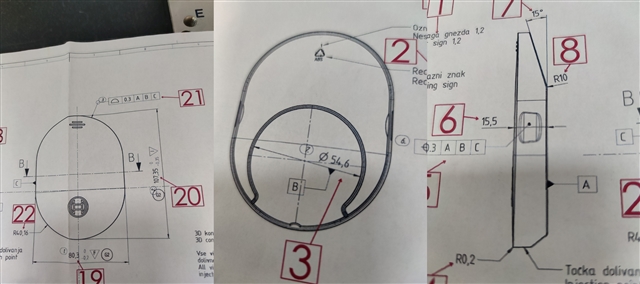
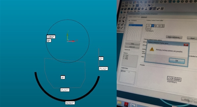
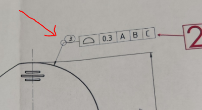
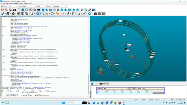
Hello guys, I would need a bit of help as I'm trying to measure this profile of surface dimension. I've been using Hexagon Performance 7.10.7 CMM machine for about 5 months, but this is the first project in which I need to measure profile of surface depended on three datum sufaces A/B/C. For datum A, I tried taking the line of surface, than making a plane, but it always shows me that axis on datum A and datum C are parallel or coincident. Datum B is I assume the circle which I scan and than make constructed circle. For the measurement I scan the radius and use that scan to get profile of surface. 

Can you help me on how to take datums A,B,C and is it correct to scan the radius and use it for my dimension. 


Parents
  • Looks like you need a plane with at least 4 points for datum A (6+ would be better) then a Circle for the diameter of datum B, and a line or plane for datum C.

  • When I do that, it says first and third plane axis are parallel and it won't let me get the measurement

  • Are you doing it like I mentioned in my post? They should not be parallel, but perpendicular. Are you using the face with the Recycle symbol for Datum A? It is showing the side of the part, but the datum triangle is pointing towards the face. Similar to how C is showing the other face of the part, but the Datum triangle is pointing to the "left" or away from the face, to the side of the part.

  • Yah I'm lost too... Those should be perpendicular. 
    Post your code.

  • I did exactly as you told and with or without alignment it says they are parallel. 

  • STARTUP =ALIGNMENT/START,RECALL:USE_PART_SETUP,LIST=YES
    ALIGNMENT/END
    MODE/MANUAL
    FLY/ON
    FORMAT/TEXT,OPTIONS, ,HEADINGS,SYMBOLS, ;MEAS,NOM,DEV,TOL,OUTTOL, ,
    LOADPROBE/ZVEZDA RAZLICITA
    TIP/T1A0B0, SHANKIJK=0, 0, 1, ANGLE=0

    PLN1 =FEAT/CONTACT/PLANE/DEFAULT,CARTESIAN,OUTLINE,LEAST_SQR
    THEO/<176.5431,76.0469,-631.9672>,<0,0,1>
    ACTL/<205.2684,66.9443,-642.2566>,<-0.0149829,-0.0185292,0.9997161>
    TARG/<176.5431,76.0469,-631.9672>,<0,0,1>
    ANGLE VEC=<0.9995163,0,-0.0311005>,SQUARE
    SHOW FEATURE PARAMETERS=NO
    SHOW CONTACT PARAMETERS=YES
    NUMHITS=3,NUMROWS=3
    SPACER=0
    AVOIDANCE MOVE=BOTH,DISTANCE=10
    USE BOUNDARY OFFSET=NO
    SHOW HITS=NO

    PLN2 =FEAT/CONTACT/PLANE/DEFAULT,CARTESIAN,OUTLINE,LEAST_SQR
    THEO/<176.5431,76.0469,-631.9672>,<0,0,1>
    ACTL/<253.7335,89.8507,-635.6324>,<0.9967371,-0.0200802,0.078179>
    TARG/<176.5431,76.0469,-631.9672>,<0,0,1>
    ANGLE VEC=<0.9995163,0,-0.0311005>,SQUARE
    SHOW FEATURE PARAMETERS=NO
    SHOW CONTACT PARAMETERS=YES
    NUMHITS=3,NUMROWS=3
    SPACER=0
    AVOIDANCE MOVE=BOTH,DISTANCE=10
    USE BOUNDARY OFFSET=NO
    SHOW HITS=NO

    CIR2 =FEAT/CONTACT/CIRCLE/DEFAULT,CARTESIAN,OUT,LEAST_SQR
    THEO/<176.5431,76.0469,-631.9672>,<0,0,1>,50,6
    ACTL/<214.4606,109.8673,-631.9672>,<0,0,1>,54.8891,6
    TARG/<176.5431,76.0469,-631.9672>,<0,0,1>
    START ANG=0,END ANG=360
    ANGLE VEC=<0.9995163,0,-0.0311005>
    DIRECTION=CCW
    SHOW FEATURE PARAMETERS=NO
    SHOW CONTACT PARAMETERS=YES
    NUMHITS=10,DEPTH=5,PITCH=0
    SAMPLE METHOD=SAMPLE_HITS
    SAMPLE HITS=0,SPACER=0
    AVOIDANCE MOVE=BOTH,DISTANCE=10
    FIND HOLE=DISABLED,ONERROR=NO,READ POS=NO
    SHOW HITS=NO

    A1 =ALIGNMENT/START,RECALL:STARTUP,LIST=YES
    ALIGNMENT/LEVEL,ZPLUS,PLN1
    ALIGNMENT/TRANS,ZAXIS,PLN1
    ALIGNMENT/TRANS,ZAXIS,PLN1
    ALIGNMENT/ROTATE,XPLUS,TO,PLN2,ABOUT,ZPLUS
    ALIGNMENT/TRANS,XAXIS,PLN2
    ALIGNMENT/TRANS,XAXIS,CIR2
    ALIGNMENT/TRANS,YAXIS,CIR2
    ALIGNMENT/END

    MODE/DCC
    SCN1 =FEAT/SCAN,LINEAROPEN,NUMBER OF HITS=460,SHOW HITS=NO,SHOWALLPARAMS=YES
    EXEC MODE=NORMAL, NOMS MODE=MASTER,CLEARPLANE=NO,SINGLE POINT=NO,THICKNESS=0
    FINDNOMS=5,SELECTEDONLY=NO,USEBESTFIT=NO,PROBECOMP=NO,AVOIDANCE MOVE=NO,DISTANCE=0.1,CAD Compensation=NO,4-axis scan=NO
    DIR1=LINE,INCR=0.3
    HITTYPE=VECTOR
    INITVEC=0.9809406,-0.1935739,0.0168709
    DIRVEC=-0.843607,-0.5369611,-0.0001197
    CUTVEC=0.0131582,-0.0204496,-0.9997043
    ENDVEC=-0.9949033,-0.1002273,-0.0110448
    PLANEVEC=0.0999718,-0.9947544,0.0216642
    POINT1=252.6061,65.0968,-639.9733
    POINT2=174.3097,71.8329,-639.9944
    MEAS/SCAN
    BASICSCAN/LINE,NUMBER OF HITS=460,SHOW HITS=NO,SHOWALLPARAMS=YES
    <252.6061,65.0968,-639.9733>,<174.3097,71.8329,-639.9945>,CutVec=0.0131582,-0.0204496,-0.9997043,DirVec=-0.843607,-0.5369611,-0.0001197
    InitVec=0.9809406,-0.1935739,0.0168709,EndVec=-0.9949032,-0.1002274,-0.0110448,THICKNESS=0
    FILTER/DISTANCE,0.3
    EXEC MODE=NORMAL
    BOUNDARY/PLANE,<174.3097,71.8329,-639.9945>,PlaneVec=0.0999719,-0.9947544,0.0216642,Crossings=1
    HITTYPE/VECTOR
    NOMS MODE=MASTER
    ENDSCAN


    ENDMEAS/DATDEF/FEATURE=PLN1,A
    DATDEF/FEATURE=CIR2,B
    DATDEF/FEATURE=PLN2,C

  • your theo vectors of plane2 are wrong.

    THEO/<176.5431,76.0469,-631.9672>,<0,0,1>
    ACTL/<253.7335,89.8507,-635.6324>,<0.9967371,-0.0200802,0.078179>

Reply Children
  • When I do it, it works but my dimension is 0.000

  • you should remeasure your datums after your manual alignment and make a new alignment with your dcc datums. you also need to scan the hole contour on several levels not just the one radius.

  • So do my datums manualy, make alignments than do them in dcc mode and do new alignments?

  • Is there any other way to do this? 

    I follow all your instructions, it looks good on paper, but measurements are just too much off. I don't get anywhere near 0.3. 

  • After your first DCC, did you do another round of DCC measurements? The first DCC alignment for me is finding all the features, then second DCC is fine tuning. See if this improves your measurements. Send your program in a reply inside of a code tag. Below the reply box, select Insert > Code. That way it's more readable

  • I would abandon your scan of datum B until you have your actual alignment locked down, there is no need to scan it for now. Seems like your current alignment is unstable and giving you pretty poor results. 

  • Not a single thing I tried has worked for me. I'm over my head with this. My scan, circle B, planes A,C look great in PCDMIS, but I'm having issues with alignment. Is there any other way to try aligning these surfaces? 

    Plane A - vectors 0,0,1 

    Circle B - vectors 0,0,1 

    Plane C - vectors 1,0,0 

    Scan - vectors 0,0,1 

    Is this okay, or should it be changed? I get dimensions like 126, 204 and I use legacy dimensions, select profile surface, set datums on these surfaces and select the scan for measurement. 

  • Well... There are some things to try assuming you didn't get this fixed yet. 

    Is your trihedron correctly aligned to your machine before you are starting the alignment?
    Did you try it without using a scan? 
    Is the part secure on the CMM, it's not sliding around, even slightly?
    You can post your most recent attempt at measurement using the insert code function below. 

  • You should have something like this...

    PLN_A      =FEAT/CONTACT/PLANE/DEFAULT,CARTESIAN,OUTLINE,LEAST_SQR
                THEO/<0,48,0>,<0,0,1>
                ACTL/<0,48,0>,<0,0,1>
                TARG/<0,48,0>,<0,0,1>
                ANGLE VEC=<0,1,0>,SQUARE
                SHOW FEATURE PARAMETERS=NO
                SHOW CONTACT PARAMETERS=NO
    CYL_B      =FEAT/CONTACT/CYLINDER/DEFAULT,CARTESIAN,IN,LEAST_SQR
                THEO/<0,0,0>,<0,0,1>,54.6,15.5
                ACTL/<0,0,0>,<0,0,1>,54.6,15.5
                TARG/<0,0,0>,<0,0,1>
                START ANG=-45,END ANG=225
                ANGLE VEC=<1,0,0>
                DIRECTION=CCW
                SHOW FEATURE PARAMETERS=NO
                SHOW CONTACT PARAMETERS=NO
    PLN_C      =FEAT/CONTACT/PLANE/DEFAULT,CARTESIAN,OUTLINE,LEAST_SQR
                THEO/<-40.15,22.6,-7.5>,<-1,0,0>
                ACTL/<-40.15,22.6,-7.5>,<-1,0,0>
                TARG/<-40.15,22.6,-7.5>,<-1,0,0>
                ANGLE VEC=<0,0,1>,SQUARE
                SHOW FEATURE PARAMETERS=NO
                SHOW CONTACT PARAMETERS=NO
    A1         =ALIGNMENT/START,RECALL:STARTUP,LIST=YES
                  ALIGNMENT/LEVEL,ZPLUS,PLN_A
                  ALIGNMENT/ROTATE,XMINUS,TO,PLN_C,ABOUT,ZPLUS
                  ALIGNMENT/TRANS,XAXIS,CYL_B
                  ALIGNMENT/TRANS,YAXIS,CYL_B
                  ALIGNMENT/TRANS,ZAXIS,PLN_A
                ALIGNMENT/END
                DATDEF/A,FEATURES=PLN_A,,
                DATDEF/B,FEATURES=CYL_B,,
                DATDEF/C,FEATURES=PLN_C,,
    SCN1       =FEAT/SCAN,FREEFORM,NUMBER OF HITS=154,SHOW HITS=NO,SHOWALLPARAMS=NO
                MEAS/SCAN
                  BASICSCAN/FREEFORM,NUMBER OF HITS=154,SHOW HITS=NO,SHOWALLPARAMS=NO
                  ENDSCAN
                ENDMEAS/
    SCN2       =FEAT/SCAN,FREEFORM,NUMBER OF HITS=154,SHOW HITS=NO,SHOWALLPARAMS=NO
                MEAS/SCAN
                  BASICSCAN/FREEFORM,NUMBER OF HITS=154,SHOW HITS=NO,SHOWALLPARAMS=NO
                  ENDSCAN
                ENDMEAS/
    SCN3       =FEAT/SCAN,FREEFORM,NUMBER OF HITS=154,SHOW HITS=NO,SHOWALLPARAMS=NO
                MEAS/SCAN
                  BASICSCAN/FREEFORM,NUMBER OF HITS=154,SHOW HITS=NO,SHOWALLPARAMS=NO
                  ENDSCAN
                ENDMEAS/
    SCN4       =FEAT/SET,CARTESIAN
                THEO/<-0.261,22.426,-7.5>,<0,0,1>
                ACTL/<-0.261,22.426,-7.5>,<0,0,1>
                CONSTR/SET,BASIC,SCN1,SCN2,SCN3,,
    FCFPROF1 =SURFACE PROFILE : SCN4
                FEATCTRLFRAME/SHOWPARAMS=YES,SHOWEXPANDED=YES,
                CADGRAPH=OFF,REPORTGRAPH=OFF,TEXT=OFF,MULT=10.00,ARROWDENSITY=100,OUTPUT=BOTH,UNITS=MM,
                COMPOSITE=NO,
                CUSTOMIZED DRF=NO
                STANDARDTYPE=ASME_Y14_5
                  PRIMARY DIMENSION/PROFILE OF SURFACE,0.3,<UZ>,<UTol>,A,B,C
                  NOTE/FCFPROF1
                FEATURES/SCN4,,
    DIM PROF4= PROFILE OF SURFACE OF SET SCN4    FORMANDLOCATION  UNITS=MM ,$
    GRAPH=OFF  TEXT=OFF  MULT=10.00  ARROWDENSITY=100  OUTPUT=BOTH
    AX    NOMINAL       +TOL       -TOL       MEAS        DEV     OUTTOL
    M        0.000      0.150      0.150      0.000      0.000      0.000 ----|----

    I've included both XactMeasure (feature control frame) and legacy profile of a surface - ideally, you should use XactMeasure.  XactMeasure will create it's ownm internal alignment from the datums whereas legacy uses the active alignment in your program.

    This is what it looks like in PC-DMIS...