hexagon logo

Position to Cast Points at different Radial Distances

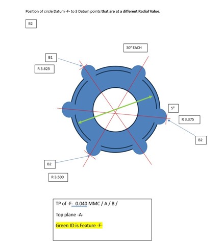
Feature control frame asks Position of ID to Top Plane -A- and -B-. Datum -B- is 3 datum target points all at different radial distances. Would Datum -B- just be reported as separate points or do you combine all 3 for a feature? Thanks for any help.

Parents
  • Datum targets are to be construed as one feature of size. Combine all three to make one diameter. Unless this is some weird elliptical/eccentric oil pump or other weird design with an intentionally not concentric set of features... i would make sure my B origin stays concentric with the rest of the part, by using basic offset values if the B datum radii are different.

  • Ok, so changing the Basic Radial distances to make them all the same is ok? I will try that and see what happens. Thank you.

  • Strike all that. lol. lemme Re-phrase, now that I noticed your basic Radii.

    First off, the drawing implies a common origin (a datum for the datum) if each B target has a radius from a unknown origin point how do you correlate them?!

    So from that implied common origin, presuming the ID?  Measure a circle for each "tooth". construct a 2d line from implied origin to each tooth's center.  then construct a generic point that's along that line + each tooth's radius to get each datum target point.

    Then, take those points and basic-offset a generic point B1 inboard by 0.25 (to make a theo of 3.375 r), and B2 (bottom one) inboard by 0.125 (to make a theo of 3.375r as well).   Origin to those points as B.  it should be concentric to your implied origin.

    Measure F from there.

  • Why not just keep it simple and align the part to A-F-C assuming C will stop rotation, and the just dimension back to datum B "circle" created from the 3 targets? Kind of thinking the drafter intended the three center points to be the targets here?

    The FCF will ignore your alignment anyways so why fuss over it because its "more proper."

Reply Children