hexagon logo

CAD import and measurement

Hello guys,

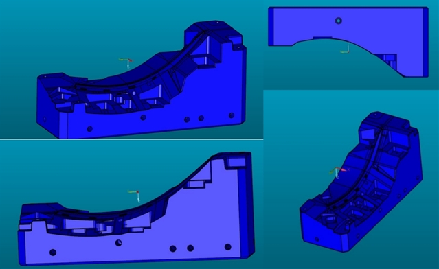
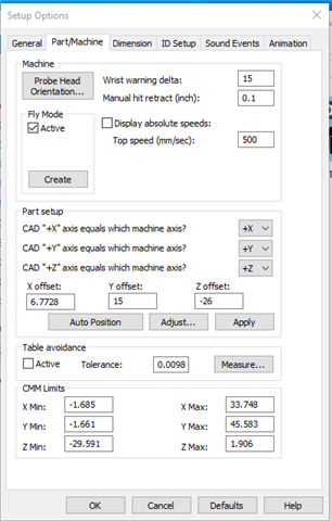
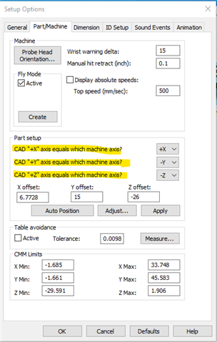
This is the first time I'm importing CAD file into PCDMIS 2018 r2 and I have to check dimensions of part on machine to see if they are in tolerance. After I import my CAD file, how do I align it with the part that is on the machine so I can do the measurements? What is the best strategy?

Parents
  • You can either do it with a read point, and then a readpoint alignment. Or if you are used to doing manual alignments and taking hits off the part. You measure your alignment features, then do your actual alignment, and then select CAD = PART. I use readpoints typically, and program from offline vs doing manual alignments personally.

  • This is my cad model and coordinate system when I import it into pcdmis. My actual part is on CMM is placed as on the picture down left. How do I transform coordinate system to other point on my CAD model? How to I align it with my actual part than? I tried using manual alignment and transform CAD model to part but it didn't work as I assume because coordinate system is upside down as axis Z is facing down. 

  • There are several ways to do this, but the first thing I would check to see of the part/machine axis are configured to your part.

    Go To setup options (F5), Part/Machine tab, Part Setup, change the CAD AXIS to the Machine AXIS

    .

    By doing this, it will 'change' the vector of the points you use for your manual alignment

    Then you can perform a manual alignment to the features you have measured, or perform a Read Point alignment.

Reply
  • There are several ways to do this, but the first thing I would check to see of the part/machine axis are configured to your part.

    Go To setup options (F5), Part/Machine tab, Part Setup, change the CAD AXIS to the Machine AXIS

    .

    By doing this, it will 'change' the vector of the points you use for your manual alignment

    Then you can perform a manual alignment to the features you have measured, or perform a Read Point alignment.

Children