Just curious about how I would scan a camshaft profile? Not even sure where to start
Your Products have been synced, click here to refresh
Just curious about how I would scan a camshaft profile? Not even sure where to start
Do you have a CAD model? If not, you will probably need some sort of text file that defines the nominal shape. Be aware though, quite often the text files supplied for the cam profile are based on the path and geometry of the tracer so they do not directly match the shape of the surface that you need to scan.
For information on scanning in PC-DMIS see: Scanning Your Part
what if he does have a CAD file Neil? how would you proceed?
With CAD, creating the scan is much easier - the help file section I linked to explains how to scan. Obviously, that's only for satisfying the profile of a surface callout that's shown in his screenshot. Camshafts usually require additional information to be reported, some of which there is no way to do in PC-DMIS. Quindos is our usual recommendation for these types of "special geometry" cases, it has a dedicated Camshaft solution.
QUINDOS PowerTrain | Hexagon
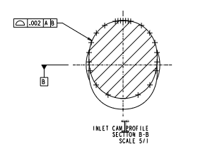
This camshaft has two lobes and both of them are called out as a profile to the cad model with no other information. thank you I will take a look at that
if i didnt have access to Quindos, and I had a CAD model, this is how I would inspect the part.
1. lay part on machine horzontal
2. grab a h/g with indicator and rotate the cam so that peak of the lobes are in the z+axis
3. evaluate datums A and B
4. measure the tops of lobes X highest surfaces using radii or a feature set.
5. pull the highest points from the feature sets and create a best fit alignment
6. evaluate the rest of the cam surfaces with scans and report profile
© 2025 Hexagon AB and/or its subsidiaries. | Privacy Policy | Cloud Services Agreement |