Hello everyone,
We are having trouble measuring the part. There are big diferences between our and customer's measurements. The customer is using PolyWorks.
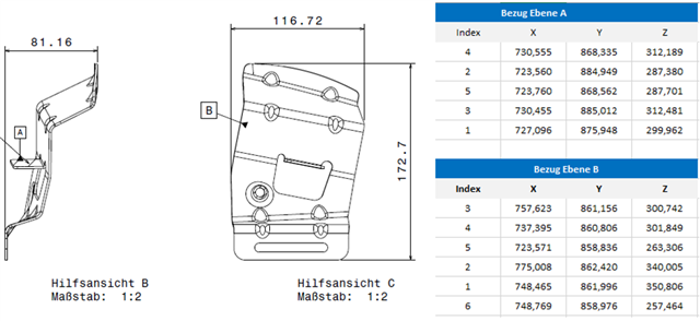
I received point coordinates for plane A (5 points) and B (6 points) from a customer (see picture below). For Plane B he also wrote "the plane is on the cylinder with Ø3,5m and we made a plane with 6 points"
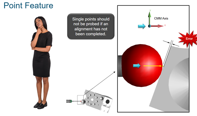
How to do iterative alignment correctly?
My alignments:
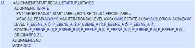
Many thanks.