So, I am using a romer arm to measure concentricity of two holes. With a traditional CMM (and different software) we have found the concentricity of the holes to be 0.26mm. However, with the romer arm it shows the concentricity to be 2.9mm. If you take the acuals from the two holes and calculate the concentricity it should read like the traditional CMM???? Why is PC DMIS not giving me the correct reading? Any suggestions on how to measure this dimension with the Romer ARM?
So, I am using a romer arm to measure concentricity of two holes. With a traditional CMM (and different software) we have found the concentricity of the holes to be 0.26mm. However, with the romer arm it shows the concentricity to be 2.9mm. If you take the acuals from the two holes and calculate the concentricity it should read like the traditional CMM???? Why is PC DMIS not giving me the correct reading? Any suggestions on how to measure this dimension with the Romer ARM?
A nice fat Friday the 13th softball? Sure. . . I'll take a swing. . .
Pc-Dmis does not calculate concentricity properly per ASMEY 14.5M 1994/2009. The only way to properly check concentricity per the standard requires the part to be rotated about the datum axis and two dial indicators applied to the surface of the feature being evaluated.
But fear not! Most of the time when the concentricity symbol is placed on a drawing it is used incorrectly and what the designer is really trying to control is position.
Pc-Dmis treats concentricity as if it were position.
There are exactly 42,555,069 posts to date about concentricity on various CMM forums should you care to spend the rest of the day reading about exactly why CMMs can't "do" concentricity right, and elaborate possible ways to get sorta close with a CMM.
But fear not! Most of the time when the concentricity symbol is placed on a drawing it is used incorrectly and what the designer is really trying to control is position.
Hey - this symbol shows 2 circles on the same centerline - that's exactly what I need! What's this called...... concentricity? I'm using that!
Seriously though, you are right. It's a rare case where concentricity could not be replaced by position or runout.
So, I am using a romer arm to measure concentricity of two holes. With a traditional CMM (and different software) we have found the concentricity of the holes to be 0.26mm. However, with the romer arm it shows the concentricity to be 2.9mm. If you take the acuals from the two holes and calculate the concentricity it should read like the traditional CMM???? Why is PC DMIS not giving me the correct reading? Any suggestions on how to measure this dimension with the Romer ARM?
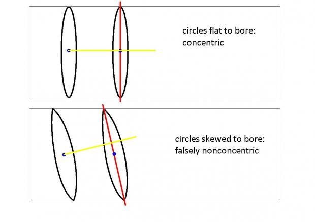
I've seen a lot of falsely designed concentricities in my time. Make sure you're leveling correctly, or you risk the following:
Unfortunately, the call out is a true concentricity. S, I guess I will have to go to my management group and tell them that the $60,000 we spent on this equipment is not capable of a simple concentricity check In a couple of the 42 million posts, there is comment about using code to make up the check. Do you know how to make this happen?
As for the cost of the equipment.... that thing is a MANUAL machine. You must control it, it will not do it for you, and all it takes is a little slop on the part of the operator and all the data is bogus.
Might be a dumb question, but are you selecting your features in the correct order? For example, the "datum" feature should be chosen second or PC-DMIS will calculate the results really funky. Also, if you're using an arm, have you made sure to set the proper probe comp by taking your first feature hit perpendicular to the surface? Not trying to be a wise guy, or doubt your skill, but I've seen these two factors come into play way too many times. Unless you're hammering the probe along your path, I would definitely excpect better results than those you reported.
I'll try selecting the datum feature secondly; however, from Wes's response, I thought I couldn't check concentricity with PC DMIS??? Thanks for the input. I understand the proper way to take the hits on the part. We just changed software from Power Inspect to PC DMIS and I am still working on the programming side of the software. Thanks.
You can check concentricity with PCDMIS, BUT it reports it according to ISO standards. That is, it reports concentricity as TP (position).
Lots of luck.
I have been reading a bunch of stuff and no one can explain this simply to me. I just want to know how to calculate this number. Basically anything I read says make sure it is centered. I don't want English I want math!!
But your post is perfecT!! I can calculate true position [tp = sqrt(x^2+y^2)*2] with calipers on our car part. Thanks for also explaining it is ISO.
Occam's Razor: I'll bet that either the CMM's part alignment doesn't match the Romer's part alignment, or the CMM circle doesn't match the Romer circle, most likely in height.
either that or there is significant operator error in the Romer's circle (shanking out).