I'm wondering if this is a CAD issue rather than anything with PC-Dmis or my Romer, but I ran two similar parts, both with slots in them. On one part the slots came out fine, on the other, the slots were perpendicular to how they were supposed to be (so the width of the CAD slot has now become the length and the length is now very short). I tried letting PC-Dmis figure out what I was creating, I tried starting from different areas. Eventually, I gave up and programmed it without CAD. Any idea what I may have done wrong?
It could be the order/direction you are taking your hits. Make sure to take hits on longest side of the slot first and move in a circular direction.
The other possibility could be your CAD vectors are incorrect. Go to Edit/Graphics Display Window and select CAD Vectors. Highlight your CAD and see what direction the vectors are at on your slot. If needed, hit Fix Surface Vectors.
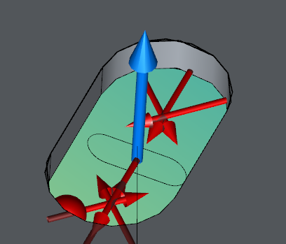
Thanks for the tip, bharpold. I tried that and the vectors appeared to be right, but that is something to consider in the future. I tried checking it in the cad before I created an alignment and this is how it appears.
I didn't notice the probe looks like it's coming through the part. Interesting.
If you don't have an alignment there will be no relationship to the probe and part. I see the slot is not right but if you don't have an alignment set with the correct work plane it would definitely cause this. Are you using auto features?


 I didn't notice the probe looks like it's coming through the part. Interesting.