There isn't a way to model from pointcloud in PC-DMIS. You will have to export either the point cloud or surface mesh and model it with a different software. If you are working with Solidworks, I would avoid using surface mesh (stl) files.
Keep in mind, laser scanning generally does not do well with thin sheet metal, unless your using a software like Polyworks. If the flat pattern is not too complex, instead of scanning, I would measure as many primitive features as possible (lines, circles, slots, ect.), then export the measured items as .igs file, and sketch the rest of it together in another CAD software.
1) Manual Alignment to the part. In this case I did a simple Plane-Line-Line so set my x/y axis for a few reasons, one of which is to show where the part really is and the other is so that I can zoom to the part quickly without having to scroll all over creation to find it.
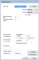
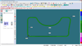
2) Manual, variable delta scan. This gives me all the little radii and angles that my programmers need.
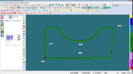
3) I then create a constructed filter feature to give me my profile line instead of all the points ensuring that the linear button is selected. I have not been able to figure out the difference between the Gaussian and Spline options. Both seem to work for my purposes
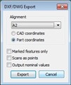
4) export the file as a dxf cad file. My programmers can then use this to make their model. I ensure that the alignment is correct and the "scans as points" option is unchecked.
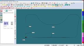
5) which brings me back to my problem. This will work for my programmers but , although you can't really see it, my profile line is offset from the lines for my alignment. In this case about .059" or 1.5mm... half the probe diameter. I have toyed with probe comp on/off to no avail and would love to figure out how to rectify the offset problem. Hope this helps someone else out there and if you have any ideas on how to get the last little bit of my problem I would love to hear from you.
1) Manual Alignment to the part. In this case I did a simple Plane-Line-Line so set my x/y axis for a few reasons, one of which is to show where the part really is and the other is so that I can zoom to the part quickly without having to scroll all over creation to find it.
2) Manual, variable delta scan. This gives me all the little radii and angles that my programmers need. {"alt":"Click image for larger version Name:\tvariable delta scan.png Views:\t1 Size:\t46.3 KB ID:\t401836","data-align":"none","data-attachmentid":"401836","data-size":"thumb"}{"alt":"Click image for larger versionName:\tscan.pngViews:\t1Size:\t25.0 KBID:\t401837","data-align":"none","data-attachmentid":"401837","data-size":"full"}
3) I then create a constructed filter feature to give me my profile line instead of all the points ensuring that the linear button is selected. I have not been able to figure out the difference between the Gaussian and Spline options. Both seem to work for my purposes {"alt":"Click image for larger version Name:\tconstructed filter feature.jpg Views:\t1 Size:\t34.3 KB ID:\t401838","data-align":"none","data-attachmentid":"401838","data-size":"thumb"}{"data-align":"none","data-attachmentid":"401839","data-size":"full"}
4) export the file as a dxf cad file. My programmers can then use this to make their model. I ensure that the alignment is correct and the "scans as points" option is unchecked.
{"alt":"Click image for larger version Name:\texport1.jpg Views:\t1 Size:\t15.5 KB ID:\t401840","data-align":"none","data-attachmentid":"401840","data-size":"thumb"}
5) which brings me back to my problem. This will work for my programmers but , although you can't really see it, my profile line is offset from the lines for my alignment. In this case about .059" or 1.5mm... half the probe diameter. I have toyed with probe comp on/off to no avail and would love to figure out how to rectify the offset problem. Hope this helps someone else out there and if you have any ideas on how to get the last little bit of my problem I would love to hear from you.
In your "variable delta" window, you do NOT have probe comp marked, thus the probe radius error.
I don't think you WANT it marked as how does Pcdmis know which way to comp the probe? Without a cad model for it to pull vectors from, you have no control over which way it will comp for the radius.
1) Manual Alignment to the part. In this case I did a simple Plane-Line-Line so set my x/y axis for a few reasons, one of which is to show where the part really is and the other is so that I can zoom to the part quickly without having to scroll all over creation to find it.
2) Manual, variable delta scan. This gives me all the little radii and angles that my programmers need. {"alt":"Click image for larger version Name:\tvariable delta scan.png Views:\t1 Size:\t46.3 KB ID:\t401836","data-align":"none","data-attachmentid":"401836","data-size":"thumb"}{"alt":"Click image for larger versionName:\tscan.pngViews:\t1Size:\t25.0 KBID:\t401837","data-align":"none","data-attachmentid":"401837","data-size":"full"}
3) I then create a constructed filter feature to give me my profile line instead of all the points ensuring that the linear button is selected. I have not been able to figure out the difference between the Gaussian and Spline options. Both seem to work for my purposes {"alt":"Click image for larger version Name:\tconstructed filter feature.jpg Views:\t1 Size:\t34.3 KB ID:\t401838","data-align":"none","data-attachmentid":"401838","data-size":"thumb"}{"alt":"Click image for larger version Name:\timage_12747.jpg Views:\t1 Size:\t6.6 KB ID:\t401839","data-align":"none","data-attachmentid":"401839","data-size":"full"}
4) export the file as a dxf cad file. My programmers can then use this to make their model. I ensure that the alignment is correct and the "scans as points" option is unchecked.
{"alt":"Click image for larger version Name:\texport1.jpg Views:\t1 Size:\t15.5 KB ID:\t401840","data-align":"none","data-attachmentid":"401840","data-size":"thumb"}
5) which brings me back to my problem. This will work for my programmers but , although you can't really see it, my profile line is offset from the lines for my alignment. In this case about .059" or 1.5mm... half the probe diameter. I have toyed with probe comp on/off to no avail and would love to figure out how to rectify the offset problem. Hope this helps someone else out there and if you have any ideas on how to get the last little bit of my problem I would love to hear from you.
Without CAD you will not be able to compensate for probe radius. Your programmers will need to offset the spline 1.5mm (.0591") to compensate for probe radius. The points you take in the scan are at the center of the probe. Your alignment features are compensated for, which gives the appearance of a mismatch between features and scan.