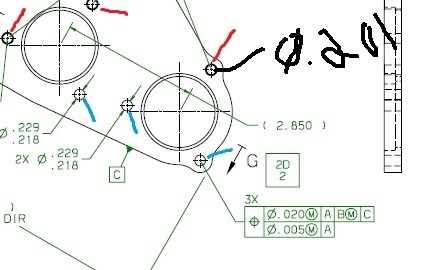
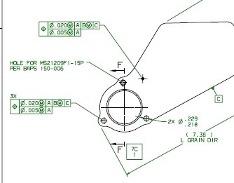
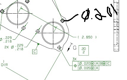
The above callout isn't seeming to work well in pc-dmis and not sure if you gents would even consider this a legal callout. As you can see the FCF references three holes. Two of the holes are .218 - .229" and the third is actually a helicoil thread that has a minor diameter of .201". When I input this into pc-dmis it doesn't really work. Any ideas?
I believe you would dimension the holes I pointed out in blue for that FCF, and as you can see the ones labeled in RED have a DARK Black shade around them, I would imagine those 3 holes are threaded
Yeah, i thought of that too pacman... and yes in this particular drawing i would agree if it was a one off. The thing is it's a dash number in a large group of drawings and this is how they call them out. the smaller holes that surround the larger ones are grouped together for the FCF's. I should have given a better example but didn't realize that was how it looked until I had already made the jpg.
well you won't be able to select holes with different diameter sizes and dimension them at the same time, it wont work just as you have found out.
So if you are sure that you have to dimension the 3 holes surrounding that larger one then just dimension them individually. or do the 2 that have the same diameter and then a separate true position for the one with threads.
I haven't ran into a print that dimensions holes with different diameter sizes under the same FCF but then again I haven't been doing this for to long, and its hard to give you any other type of advice other than going about it the way I told you about up top without seeing the whole print