hexagon logo

Midpoints in bends on a tube

Hello all. I was wondering if anyone could explain how to get some of these points in this drawing, and hopefully help in getting a dimension.

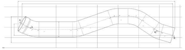
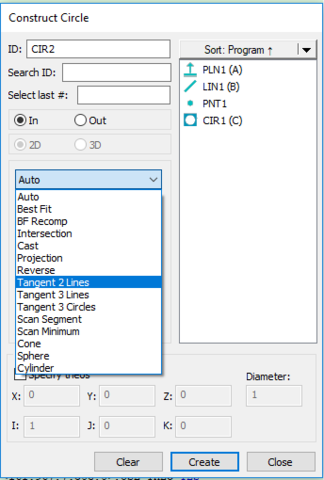
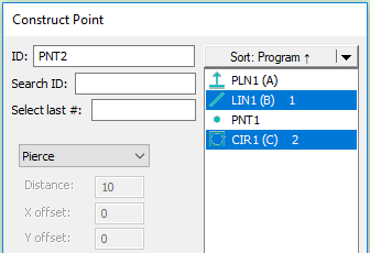
For this part, I would create a plane on the left end of the part, followed by cylinders for each straight. Then a plane on the right side. Next, I would construct a pierce point for plane 1 and cylinder 1 which would give me midpoint 1. Then construct an intersection point between cylinder 1 and 2, and that would be midpoint 2. I would continue this for the rest of the tube until i get to the last pierce point giving me midpoint 7. I have learned that i can create a cast point on cylinder 2, and it will give me midpoint 2.2; however, I have not yet been able to figure out a way of getting any of the x.1 midpoints.

That is where my question starts: How can i get these .1 midpoints? I feel like I've tried every combination of picking two cylinders and all the different types of points, and have had no luck in getting them. I have XYZ coordinates for these points, but more importantly, i have length-of-straights dimensions that are taken as a measurement between for example 1 to 2.1. This is a crucial measurement to the fit/form/function of our part, and as of now, i have absolutely no way of checking it.

My second question is this: Almost every part we have has a dimension for mid 1 to mid 7 across the Y-axis (as shown). But they will also dimension in this case, the top of cylinder 1 to the bottom of cylinder 7 (relative to the Y-axis) across the Y-axis. Every time i try to measure Cyl 1 to Cyl 2 across the Y-axis (with plus diameter getting me the closest), I never can seem to quite get a passable measurement.

Any help in either of these matters would be greatly appreciated.
Parents
  • No, my method works on the centre line. The points 1, 2 and 3 in my picture are the first three centre line's intersection points, the two green points are the 'inflexion points' where the centre line passes over into an arc, and then to the next centre line.

    You need lines and an alignment to be able to construct the tangent circles and tangent points, so if you already have cylinders, you must create (cast) lines from all of them.
    Then you construct a plane from your intersection points 1, 2 and 3, and level to that (this is the plane the first bend is made in)
    Now construct a circle tangent to lines 1-2 and 2-3, with the fixed bend radius


    Then construct a pierce point from lin 1-2 and the circle (this is your point 2.1) - this is the single intersection (==tangent point) between line 1-2 and the circle, as the circle was constructed as tangenting the line
    Then construct a pierce point from lin 2-3 and the circle (this is your point 2.2)


    ...and repeat
Reply
  • No, my method works on the centre line. The points 1, 2 and 3 in my picture are the first three centre line's intersection points, the two green points are the 'inflexion points' where the centre line passes over into an arc, and then to the next centre line.

    You need lines and an alignment to be able to construct the tangent circles and tangent points, so if you already have cylinders, you must create (cast) lines from all of them.
    Then you construct a plane from your intersection points 1, 2 and 3, and level to that (this is the plane the first bend is made in)
    Now construct a circle tangent to lines 1-2 and 2-3, with the fixed bend radius


    Then construct a pierce point from lin 1-2 and the circle (this is your point 2.1) - this is the single intersection (==tangent point) between line 1-2 and the circle, as the circle was constructed as tangenting the line
    Then construct a pierce point from lin 2-3 and the circle (this is your point 2.2)


    ...and repeat
Children
No Data