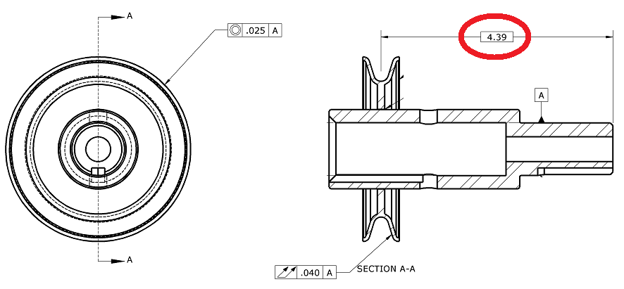
How do I use the basic [4.39] with total run-out or do I somehow add it with the concentricity? I am lost with how to measure the 4.39". I can do it with a true position but that is not an option here.
One thing is for certain the 4.39 has nothing to do with the total runout callout or concentricity. The total runout is to A only same with concentricity.
I would assume that, on the right side image, the right end of the part should be a datum - let's call it B. Position of radial groove to B should be specified to control that 4.39 dimension.
I don't know about ISO world but the drawing is non-compliant per Y14.5. Datum A is a planar feature. You need an axis about which to rotate to evaluate the total runout. I would kick this one back to the customer.
That 4.39 is only useful if there is a Profile callout for that groove, and the far right end of the part is a datum. Or it could be a gage circle location, but then there should be a size or other dimension associated with that also. If there is no other dimension for that groove somewhere else, then the 4.39 is meaningless.
Well, what does a cylinder look like when you look at it from the side? Look at the view on the left. Everything is concentric circles. If it's not a cylinder, I'd be very surprised. And, the view on the left is looking at the part from the smaller end (Datum A is facing us in the view on the left.)
There is an extension line coming off the cylinder, looks like A is pulled off of that surface
Poor drawing but only way that concentricity to A makes sense to that FCF but confusing and not sure legal because it is on surface extension not diametrical
Total run out to A then makes no sense to surface that is pointing to