hexagon logo

line profile & diameter tolerance

Hello,
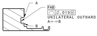
I am a new member seeking for help as I can't figure out how to go about this, please refer to the screen shot attached. both of the flag note and the line profile tolerance applied to the bottom groove, between a and b. the flagnote is to omit prime and paint


it's my first time running into a line profile with the diametrical tolerance together. I can create a Xactmeasure, but I can't find anywhere to input the diameter symbol. please excuse my lack of knowledge, but any help on this subject is greatly appreciated.

the software I am using is PC-Dmis CAD++ V2017 SP5 for Romer Arm.

thank you,
Joseph
Parents
  • Does your blueprint call out a specific GDT Interpretation spec (Y14.5 or ISO XXXX)?

    If Y14.5, I'm pretty sure the feature control frame you're showing us is invalid. My interpretation what your print is trying to say (you'd ultimately have to verify with your customer to be 100%) is:


    Symbol means line profile, number after symbol is overall amount of tolerance. The "UNILATERAL OUTWARD" not on your print makes me think they want to use the unequal tol zone symbol and for it to go OUTWARD...since they didn't specify an amount outward I assume they want the full 0.015.

    If my above logic was approved by whomever needs to sign off on it, I would then either:
    A) Do a scan from A-B and then do a Line Profile Dim as I did above.

    B) If you use legacy you could do a scan and then tolerance it with line profile command +0.015/-0.000.... OR.. use autovectorpoints and check their "T Values" using the +0.015/-0.000.
Reply
  • Does your blueprint call out a specific GDT Interpretation spec (Y14.5 or ISO XXXX)?

    If Y14.5, I'm pretty sure the feature control frame you're showing us is invalid. My interpretation what your print is trying to say (you'd ultimately have to verify with your customer to be 100%) is:


    Symbol means line profile, number after symbol is overall amount of tolerance. The "UNILATERAL OUTWARD" not on your print makes me think they want to use the unequal tol zone symbol and for it to go OUTWARD...since they didn't specify an amount outward I assume they want the full 0.015.

    If my above logic was approved by whomever needs to sign off on it, I would then either:
    A) Do a scan from A-B and then do a Line Profile Dim as I did above.

    B) If you use legacy you could do a scan and then tolerance it with line profile command +0.015/-0.000.... OR.. use autovectorpoints and check their "T Values" using the +0.015/-0.000.
Children
No Data