hexagon logo

Polygon question - hex longer than width; datum feature; True Position

First post; be gentle. …

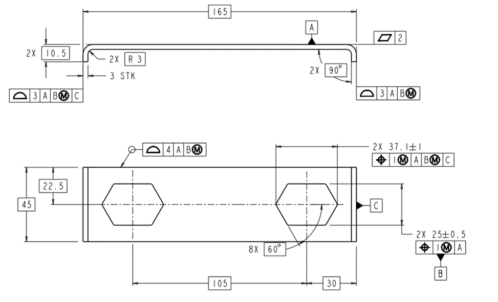
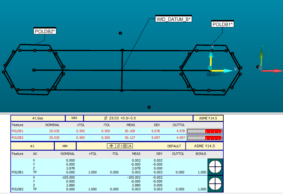
I've been given this shiny turd. The hex length is greater than the width. I've constructed a width feature across the two hex shapes to use as my Datum B "feature of size", but I'm a little stumped on how to report the TP of the polygon when it doesn't show the size properly. Have I missed some feature where I can tell PC-DMIS that the hexagon shape is longer than it is wide? You can see the points I've taken that show the true shape of the hex shape. I thought there might be a "constructed polygon" option, but I haven't found it yet.

I've searched the forum but didn't find anything like this. Most of the discussion of polygons is of regular shaped ones.


Attached Files
  • I would try to construct each corner, then construct a feature set with them and try to TP it.
    Else, construct the centroid, and TP it...
  • you could try this: (USE at your own risk)

    Have your cad person give you data with a SQUARE SLOT the same width & length of that, then program a square slot to measure it, using the WIDTH option and set the radius to an acceptable value to hit on the long flats. This will make Pcdmis measure 2 hits on each long side, then 1 hit on each end (point) centered to the width of the long sides. It will not give you the correct length, but it SHOULDl give you the correct center point. It is worth a try at least.

    You could also use all those points you are measuring, constructed lines, constructed intersection points and some additional constructed lines & points, and MAKE a generic square slot out of the data.
  • The True Position is showing correct. What I meant was how to show the size correctly as part of that Feature Control Frame reporting window. What I resorted to was reporting the length and width as separate dimensions and telling the engineer in charge of PPAP to please ignore the "out of tolerance" reported measurement.

    My main issue is that PC-DMIS, ironically, can't measure a HEXAGON properly. Rolling eyes
  • It doesn't look like you're being asked to dimension any hexagons. It looks like you have two slots that are equilateral triangles on each end.

    Create intersection points on the two lines at each end, and a midpoint between those points. Dimension the distance from intersection point to intersection point. Construct a generic circle centered on the midpoint with diameter equal to the distance.

    B can be made with a variety of different techniques.
  • Regular polygons are easy, because they are just circles with less points.
  • Well, a generic square slot created from the correct features and dimensions would show correct size and position on the report. Lots of coding, yes, but once done, no need to do it again. 12 points, 6 lines to get the 'shape'. then make 6 points where each line intersects. Make 2 lines from the 4 points at each end of the long sides (crossing the middle of the shape). Make a point where those 2 lines intersect. That is the center point of the shape. Then get the distance between both pair of points on the long sides (across the shape), use the average for the width, get the distance between the 2 end point points, that is the length. Then, make a generic square slot, using the CP and sizes, should work.
  • So, that feature is actually called a parallelogon. A parallelogon is not a standard feature of Pc-Dmis. Creative inspection methods would need applied. Creating generic features to capture extracted data from more basic features (lines/ constructed points) would be the way to go here.

  • The only things actually being toleranced are the two widths, there is nothing controlling the 60° sides (unless there is a general profile requirement somewhere else on the drawing). It looks like you're using 2020 R2 from your screenshots. If so, you can construct a 1D width feature to represent the 37.1 width. You would need to intersect the two 60° lines at each end of your shape and then construct a 1D inner width from the intersection points.
  • Pnt37 =feat/point,cartesian,no
    theo/<18.684,0,13.525>,<0.5,-0.8660254,0>
    actl/<18.684,0,13.525>,<0.5,-0.8660254,0>
    constr/point,int,lin11,lin12
    pnt38 =feat/point,cartesian,yes
    theo/<-18.684,0,13.525>,<-0.5,0.8660254,0>
    actl/<-18.684,0,13.525>,<-0.5,0.8660254,0>
    constr/point,int,lin14,lin15
    f1_37 =generic/point,dependent,cartesian,$
    nom/xyz,<pnt37.tx,pnt37.ty,pnt37.tz>,$
    meas/xyz,<pnt37.x,pnt37.y,pnt37.z>,$
    nom/ijk,<-1,0,0>,$
    meas/ijk,<-1,0,0>
    f1_38 =generic/point,dependent,cartesian,$
    nom/xyz,<pnt38.tx,pnt38.ty,pnt38.tz>,$
    meas/xyz,<pnt38.x,pnt38.y,pnt38.z>,$
    nom/ijk,<1,0,0>,$
    meas/ijk,<1,0,0>
    lenftr4-1 =feat/width,cartesian,in,yes
    theo/<0,0,13.525>,<1,0,0>,37.1
    meas/<0,0,13.525>,<1,0,0>,37.368
    constr/width,f1_38,f1_37
    pnt39 =feat/point,cartesian,no
    theo/<123.684,0,13.316>,<0.5,-0.8660254,0>
    actl/<123.684,0,13.316>,<0.5,-0.8660254,0>
    constr/point,int,lin17,lin18
    pnt40 =feat/point,cartesian,no
    theo/<86.316,0,13.759>,<-0.5,0.8660254,0>
    actl/<86.316,0,13.759>,<-0.5,0.8660254,0>
    constr/point,int,lin20,lin21
    f1_39 =generic/point,dependent,cartesian,$
    nom/xyz,<pnt39.tx,pnt39.ty,pnt39.tz>,$
    meas/xyz,<pnt39.x,pnt39.y,pnt39.z>,$
    nom/ijk,<-1,0,0>,$
    meas/ijk,<-1,0,0>
    f1_40 =generic/point,dependent,cartesian,$
    nom/xyz,<pnt40.tx,pnt40.ty,pnt40.tz>,$
    meas/xyz,<pnt40.x,pnt40.y,pnt40.z>,$
    nom/ijk,<1,0,0>,$
    meas/ijk,<1,0,0>
    lenftr4-2 =feat/width,cartesian,in,yes
    theo/<105,0,13.538>,<-1,0,0>,37.1
    meas/<105,0,13.538>,<-1,0,0>,37.368
    constr/width,f1_39,f1_40
  • Sorry I don't know how to format that, but that's what I ended up with to create the features that I could use to dimension in GeoTol.