I apologize if this has been covered. A few searches didn't quite turn up what I need. Romer arm with PC-DMIS 2020 R1. I have a pattern of slots defined as shown below. I cannot measure them as I would measure a pattern of round holes. I can measure them all individually and max material functions properly, giving me the bonus from the 0.2 tolerance, and properly measuring the position of each slot to 2mm. But I cannot group them together such that I can create a composite FCF and check them to each other. Any input would be appreciated, or a workaround if this is not something simple to do in PC-DMIS. Thank you!
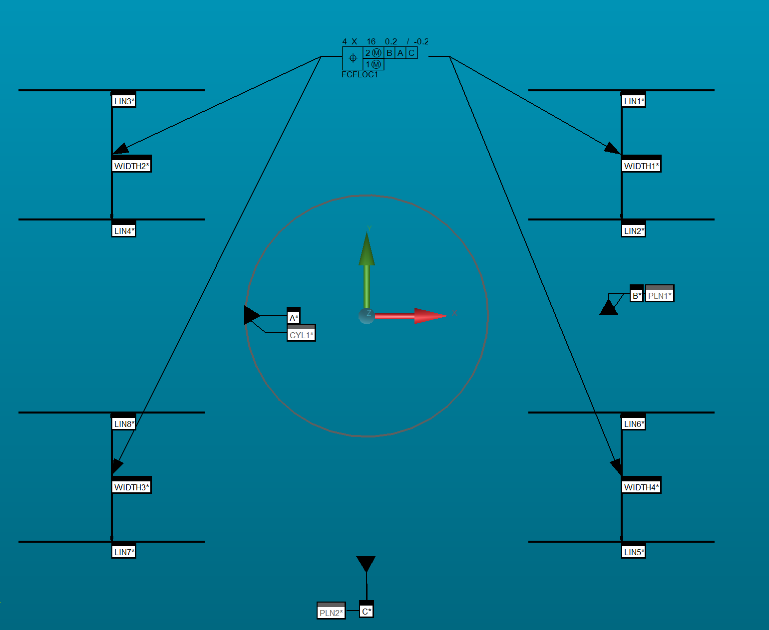
It might depend on what your datums are. I took a guess that A was a cylinder and B & C were planes. I also guessed at the slot pattern and made them equi-spaced around the cylinder. Rather than measure slots, I constructed 2D widths in the width-wise orientation and using XactMeasure I was able to do it. Here's a screenshot of the graphics window...
The reason I used widths is because XactMeasure treats slots as circles and when applying bonus it takes whichever orientation has the tightest tolerance which is not always desirable.