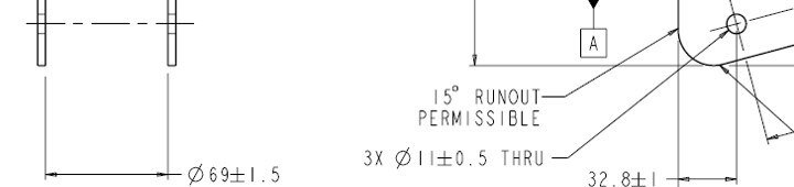
I have a part with 2 parallel vertical pieces. The print calls out 3x Ø11±0.5 THRU. How would you gentlefolk approach this? Construct a cylinder for each set and report the True Position? Report the true positions of each set of 2 circles? Construct a cylinder and define it as a datum and then report concentricity of the end circles to that datum cylinder? Or would it be better to move the origin to one of the circles and report the coaxiality of the other circle to the "origin"? If the lattermost option, what tolerance would you put on that coaxiality?
Also, while I have your attention--I've never seen "runout" on the edge of a flat part. Does this mean they are going to accept UP TO 15° from perpendicular on that edge?
I was asking about how to handle the "thru" part of the callout. It doesn't seem to be applicable. In fact, the use "thru" AND the use of "runout" on this print indicates to me that the drafter didn't understand the terminology he/she was using.
I was asking about how to handle the "thru" part of the callout. It doesn't seem to be applicable. In fact, the use "thru" AND the use of "runout" on this print indicates to me that the drafter didn't understand the terminology he/she was using.
I do not think the drawing means circular runout but more a statement that the tool producing the radius can angle off the surface at 15 deg to prevent dig in