hexagon logo

Measures in two axes - help a rookie out

Please if anyone can help a rookie..
I basically got a romer arm handed to me, and I had to learn alot by myself. Alot do makes sense, but sometimes I get really confused though PC-DMIS is not very intuitive when something goes wrong.
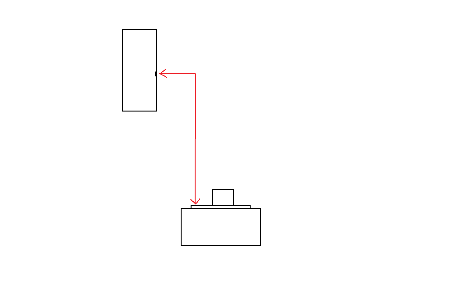
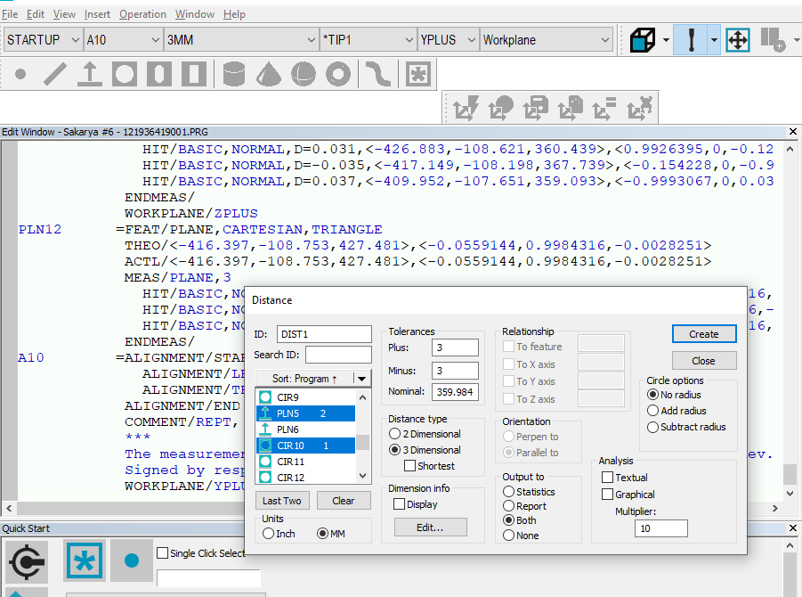
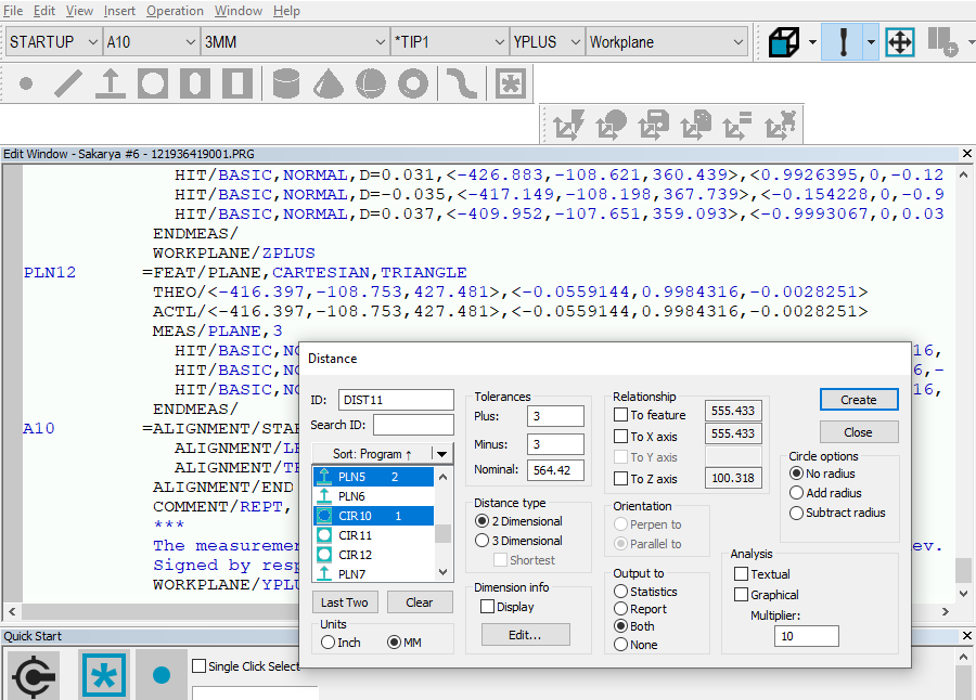
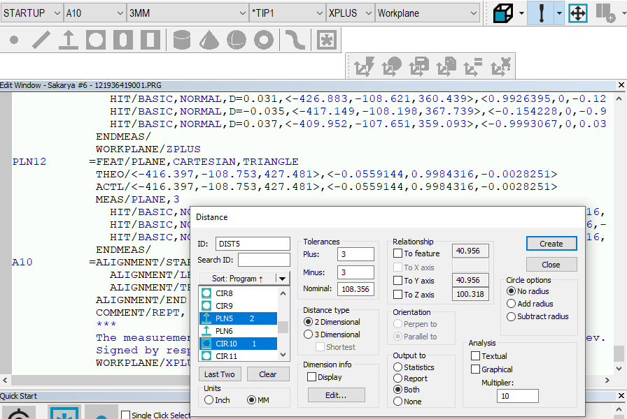
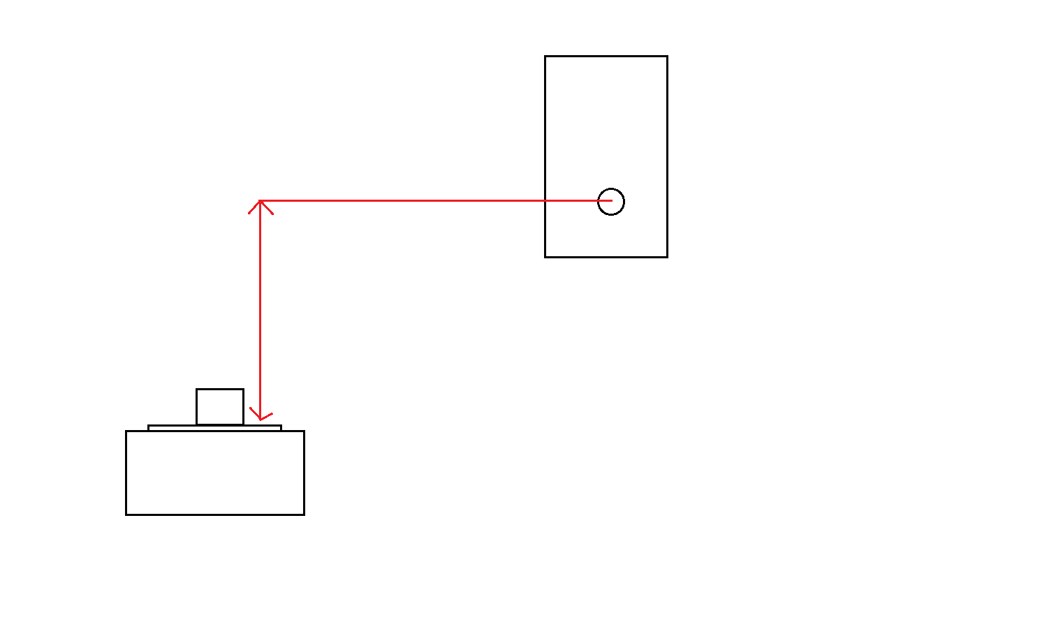
Basically I am measuring a piece which is offset and also in two different axes. I have done this several times, getting the correct results according to the drawing. At first i measure a plane and circle to align the position, leveling out Z with the plane and connects the circle to XY. The plane measured in Z to align is also the plane i want a distance from to a hole measured in Y (I have to change the view to even get a full circle in the right axis). So I want a distance from Z to Y. The plane is level to earth (xD) and the hole you can physically see in Y. OK? So why.. when it is supposed to be 320mm +- 3mm nominal, I get 327 measured value? I have checked by measuring manually, and its 322mm - perfect..
My logic wants to think that to at all be able to get right result you have to see in Y axis. Logically you can't see the hole measured in Y from Z view.

  • If you distance from a plane in Z to a hole in Y, the value is taken from the centroid of the plane to the centroid of the hole (unless you tell PC-DMIS otherwise). Your planes centroid will end up at different places each time you measure that plane. It is also giving you the shortest distance between your two features. A distance in Z (height) from the plane to the hole in Y is easy and sounds more "correct"?

    I suggest you post a crude snippet/drawing of the part and what you want to accomplish and we can take it from there.
  • A  B


    Unfortunately we cannot share any drawning, or snippet of the drawing due to company policies, so this is as good as it gets.. Look at my poorly done drawing made in paint...

    Picture A is "seen from" Y (the front), and B is seen from X (the side). What i want is the distance/height between the plane of the flange to center of the hole. As you can see on drw B, it is offset .. and I'm not sure if that has anything to do with it, but I have measured this before, and never had this problem. So I want to understand why this is happening, cause nothing in the system is telling me what the problem is.
    Please, if you don't understand this ridiculus drawing, let me have another try later.
  • If you distance from a plane in Z to a hole in Y, the value is taken from the centroid of the plane to the centroid of the hole (unless you tell PC-DMIS otherwise). Your planes centroid will end up at different places each time you measure that plane. It is also giving you the shortest distance between your two features. A distance in Z (height) from the plane to the hole in Y is easy and sounds more "correct"?

    I suggest you post a crude snippet/drawing of the part and what you want to accomplish and we can take it from there.


    I'm new to this forum, so maybe I have to quote you for you to see my reply. I'm sorry! Slight smile My reply above.
  • Yeah, it seems you want the distance in Z (not in Y).

    - Select workplane X or Y
    - Evaluate distance
    - Select "Perpendicular to" in the distance dialog
    - Select the hole first then the plane (the distance will be evaluated perpendicular to the plane)
    - Enter your nominals and tolerances in the dialog
    - Hit Create


    I am guessing you mean under "orientation" you press "Perpen to"? I'ts automatically checked on "parallel to" but I can't change it. There is a lot of trying and failing in this program, so the best would be to start all over. But why can't i chose under "Orientation"? Slight smile (The measure is supposed to be 354 +-3 and the only thing close to it is 3D dim. in Yplus)


  • Sorry, you need to select "feature" before the "Orientation" gets enabled.

    - Select workplane X or Y
    - Evaluate distance
    - Select the hole first then the plane (the distance will be evaluated perpendicular to the plane)
    - Enter your nominals and tolerances in the dialog
    - Select 2-dimensional
    - Select to feature
    - Select Perpen to
    - Hit Create​


    Aha! Thank you. Great to know Smiley
    The result is still the same though... I think I need to try to make a new program and measure everything all over again.

    This forum is great! Thanks for your kind help.
  • You can also post your code (your program) so we can see if there is any alignment issues etc. and help you even further.

    EDIT: https://www.youtube.com/watch?v=cDgj_z8Hz9M