hexagon logo

2019 R2 hasn't fixed THIS yet...... :mad:

Regarding Vision Auto Profile 2D? I'm beyond (even before that previously beyond) miffed about this 'feature'. Angry
EVERY attempt at a profile in Vision does the same thing. FACETED.
In a family of parts at my company? Faceted. I just tried on the Hexagon training block. SAME crap. WHY? See below:
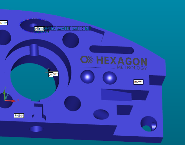
This is the normal curve; an oval from the training Hex block:


But THIS is what I get using offline Auto Profile 2D:


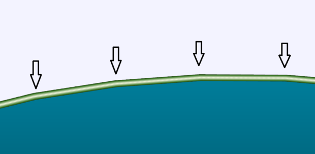
See? And I know that doesn't look too bad, BUT forget about the graphics.... on the report it shows .0001 to .0002 from nominal. The profiles on my family of parts are bilateral .002. So I'm getting jaspered off the CAD by 10-20% of the tolerance before I even REALLY check the part. Jeezus cripes! Auto Profile 2D needs to tweak it's algorithm, or SOMETHING!.
As this feature currently exists? It just plain blows chunks.

*Note: If offline profile scanned with tactile tip? Not a problem. Rolling eyes


  • I agree, 2D profile has been a thorn in the side of the vision side of the software. It works great for reverse engineering to get a general idea of what the shape of a part or tooling is. However, when it comes to real-world applications with tight tolerances, it fails immensely. This has forced me to utilize tactile probes to measure the profile of a part.
  • Does changing the tesselation value, in OpenGL options, alter the length of the segments?
  • AndersI, I have played with the tesselation to highest I can set... (.01)? I only have a mid-range Nvidia video card and have tried .stp or iges and I get faceted results. Its not so much the segment length, but
    more so the min/max and the graphical analysis for that oval in upper left:


    so I still get these strange arc'd profile! I have NO idea what is going on. Again... it only happens with Vision... with Performance 443 Dual Z Optiv the tactile scan is normal.
    Am ready for a straightjacket! Sunglasses ...........


  • Got a short summary of what you are doing in order for this to happen (step-by-step)?
  • The result looks like the *measured* profile is 'polygonized' - are there any settings in the Vision part for 'resolution', 'tesselation' or whatever? I don't have any real Vision knowledge, I'm just guessing...
  • Hi Sealevel, This should be an Offline issue only for 2D Profile. This does not affect Online measurement. Please see below for an explanation of Offline behavior:

    For offline, all the measured points are simulated points, simulated points are calculated from our Nominal Form code used for target generation. Our Nominal Form code only contains lines and circles(arcs), it doesn’t support generic curves, so for circle and line vision features you don’t see the issue in offline as the nominal form is only using the line or circle, so the simulated points are on the feature.

    For 2D profile, we have to handle generic curves, we decided to use only line sections for 2D Profile nominal form. 2D Profile contains a series of cad elements, if a cad element is a line, we add one line section into Nominal Form. If a cad element is a polyline, we add a number of lines into it. If a cad element is any other type, code will break it down to a series of lines. It will not be exactly on the feature. Because the offline simulation points are generated from Nominal Form, you see it the way you have shown above.
    Online we measure the points on the edge, so there is no problem. All measured points are either simulated points (offline) or edge points (online), then we do a cad drop to cad elements to get their respective theo points.

    I hope this clears this up. If you have any further questions, please contact me at neil.ryan@hexagon.com

    Cheers

    Neil