hexagon logo

Alignment from FCF Datum Shift


I think what vpt (and me) were hoping for was a way to create an alignment that uses the Xact fit shift. There are all sorts of applications for this. Using the available options in best-fit alignment is not the same, because they do not attempt to fit within a tolerance zone.

A few years old but I haven't found anything using search.

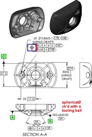
SPH1       =GENERIC/SPHERE,DEPENDENT,CARTESIAN,OUT,$
            NOM/XYZ,<0,0,0>,$
            MEAS/XYZ,<0,0,0>,$
            NOM/IJK,<0,0,1>,$
            MEAS/IJK,<0,0,1>,$
            DIAMETER/1,1.1
DIM LOC1= LOCATION OF SPHERE SPH1
AX    NOMINAL       +TOL       -TOL       MEAS        DEV     OUTTOL
D       1.0000     0.2500    -0.2500     1.1000     0.1000     0.0000 ------#--
END OF DIMENSION LOC1
            DATDEF/FEATURE=SPH1,A
            DISPLAYPRECISION/6
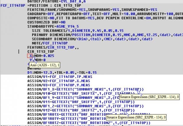
FCFLOC1 =POSITION : CIR152_1,CIR152_2,CIR152_3,...
            FEATCTRLFRAME/SHOWNOMS=NO,SHOWPARAMS=NO,SHOWEXPANDED=NO
              SIZE TOLERANCES/33,DIAMETER,0.375,0.005,-0.005
              PRIMARY DIMENSION/POSITION,DIAMETER,0.01,MMC,A,MMC,,
              NOTE/FCFLOC1
            FEATURES/CIR152_1,CIR152_2,CIR152_3,CIR152_4,CIR152_5,
                                CIR152_6,CIR152_7,CIR152_8,CIR152_9,CIR152_10,
                                CIR152_11,CIR152_12,CIR152_13,CIR152_14,
                                CIR152_15,CIR152_16,CIR152_17,CIR152_18,
                                CIR152_19,CIR152_20,CIR152_21,CIR152_22,
                                CIR152_23,CIR152_24,CIR152_25,CIR152_26,
                                CIR152_27,CIR152_28,CIR152_29,CIR152_30,
                                CIR152_31,CIR152_32,CIR152_33,,
            ASSIGN/V1=GETTEXT("DRF_SHIFTX",1,{FCFLOC1})
            ASSIGN/V2=GETTEXT("DRF_SHIFTY",1,{FCFLOC1})
            ASSIGN/V3=GETTEXT("DRF_SHIFTZ",1,{FCFLOC1})
            ASSIGN/V4=GETTEXT("DRF_ROTATIONX",1,{FCFLOC1})*-1
            ASSIGN/V5=GETTEXT("DRF_ROTATIONY",1,{FCFLOC1})*-1
            ASSIGN/V6=GETTEXT("DRF_ROTATIONZ",1,{FCFLOC1})*-1
            FORMAT/TEXT, , ,HEADINGS, , ;NOM,MEAS, , , , , 
DIM BEFORE= LOCATION OF CIRCLE CIR152_1
AX     NOMINAL        MEAS
X     10.153721   10.154507
Y    -27.402826  -27.405035
Z     -8.032519   -8.025360
END OF DIMENSION BEFORE
ALIGN1     =ALIGNMENT/START,RECALL:PREVIOUS,LIST=YES
              ALIGNMENT/ROTATE_OFFSET,V4,ABOUT,XPLUS
              ALIGNMENT/ROTATE_OFFSET,V5,ABOUT,YPLUS
              ALIGNMENT/ROTATE_OFFSET,V6,ABOUT,ZPLUS
              ALIGNMENT/TRANS_OFFSET,XAXIS,V1
              ALIGNMENT/TRANS_OFFSET,YAXIS,V2
              ALIGNMENT/TRANS_OFFSET,ZAXIS,V3
            ALIGNMENT/END
DIM AFTER= LOCATION OF CIRCLE CIR152_1
AX     NOMINAL        MEAS
X     10.151373   10.152161
Y    -27.394485  -27.396694
Z     -8.041472   -8.034312
D      0.376500    0.377383
END OF DIMENSION AFTER
            COMMENT/REPT,
            "Xshift:  "+V1
            "Yshift:  "+V2
            "Zshift:  "+V3
            "Rotation X:  "+V4*-1
            "Rotation Y:  "+V5*-1
            "Rotation Z:  "+V6*-1

The FCF output with datum shift is:


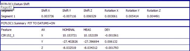
Using a sphere as the only datum seems to allow all 6 degrees to float. There is some small round-off error due to the numbers being used limited to the current DISPLAYPRECISION (not much).

Now what? Trying to actually use this has me baffled. I'd like to simulate the FCF output having the transformed measured coordinates evaluated against the model nominal values. The BEFORE dim has the nominals I want but the AFTER dim has the measured I want (like the FCF output). Inserting & Recalling alignments, Updating Dependent Commands (answering both yes and no) leaves me feeling like I've found my way into a rabbit hole. Maybe Profile dims behave differently?

I'm aware that some settings may influence the results: Update Dependent Commands (warning), UpdateBelowChangedAlignmentDuringExecution (registry), Ignore CAD to part (F5 settings), Allow Fine Tuning of Alignment (F5 settings). I'd really like to get this working inline without resorting to any type of external automation if possible. Can someone throw me a bone here? There's gotta be a way to get some mileage out of this.
  • It was from the help files, just search gettext for the full thing

    Sent from my Nexus 4 using Tapatalk
  • It was from the help files, just search gettext for the full thing

    Sent from my Nexus 4 using Tapatalk


    I think I understand... It helped to notice that I could click SHOWNONS to YES
    Then hovering over the X nominal I see it has an index number of 132.
    But I don't see where I can show the measurement results and get the index number for what the X checked after the shift.
    I see from the code I copied and pasted from GomoFazter that the measurement result index number must be 134.
    I am confused that ALL the measurement results appear to be using 134 though...
  • Kevo - I put this together as something you might be able to use as a skeleton to build on. I'm sure you will want to format the output for your upstream app. I first tried explaining it and gave up (it was easier to just code it). Diameters would need to be added if desired along with the actual TP's. I'm not very familiar with Cypress Enable but it seems to be working fine when inserted as a script command at the end of the program. It saves to the current part program folder then opens in Notepad (remove or comment out as needed). I don't know how you intend on plugging this in so stopped after extracting the coordinate values. Can you outline the data & format needed?

    Sub Main()
    	Dim oApp As Object
    	Dim oPart As Object
    	Dim oCmds As Object
    	Dim oCmd As Object
    	Dim oShell As Object
    	dim iNumCmds as Integer
    	Dim i As Integer, j As Integer
    	Dim iFeats As Integer, iVals As Integer, iSegs As Integer
    	Dim sOut As String
    	Dim sFile As String
    	Dim FF As Long
    
    	Set oApp = CreateObject("PCDLRN.Application")
    	Set oPart = oApp.ActivePartProgram
    	Set oCmds = oPart.Commands
    
    	sFile = Left(oPart.FullName, Len(oPart.FullName) - 4) & "_" & oPart.SerialNumber & "_FcfDims.txt"
    	FF = FreeFile
    	Open sFile For Output As #FF
    
    	For each oCmd in oCmds
    		If oCmd.TypeDescription = "FCF Position" And oCmd.Marked And oCmd.GetText(OUTPUT_TYPE, 1) <> "NONE" Then
    			iFeats = oCmd.GetDataTypeCount(REF_ID)  '# of features
    			iSegs = oCmd.GetDataTypeCount(DRF_SEGNAME)  '1 or 2 tier FCF
    			iVals = oCmd.GetDataTypeCount(SUMMARY_MEAS) / iFeats / iSegs  '# values per feature
    
    			sOut = oCmd.ID
    			For i = 1 To iVals
    			  sOut = sOut & "," & oCmd.GetText(SUMMARY_AXIS, i)  'X,Y,Z,PR,PA from FCF Advanced Tab
    			Next i
    			Print #FF, sOut  'output header line for dimension
    			For i = 1 To iVals * iFeats * iSegs - iVals + 1 Step iVals
    				sOut = oCmd.GetText(SUMMARY_FEAT, i)  'segment & feature name
    				For j = 0 To iVals - 1
    					sOut = sOut & "," & oCmd.GetText(SUMMARY_MEAS, i + j)  'all values for this segment of this feature
    				Next j
    				Print #FF, sOut  'output all values for each feature in each segment
    			Next i
    		End If
    	Next oCmd
    	Close #FF
    
    	Set oShell = CreateObject("WScript.Shell")
    	oShell.Run "notepad.exe " & sFile
    
    	Set oShell = Nothing
    	Set oCmd = Nothing
    	Set oCmds = Nothing
    	Set oPart = Nothing
    	Set oApp = Nothing
    End Sub


    The output would look something like:
    FCFLOC2,X,Y,Z,PR,PA
    Segment 1:CIR3,3.6689,0.7566,0,3.7461,11.6516
    Segment 1:CIR4,6.0651,0.756,0,6.1121,7.1055
    Segment 1:CIR5,6.0596,3.1535,0,6.8311,27.4931
    Segment 1:CIR6,3.6607,3.1513,0,4.8303,40.7229
    Segment 2:CIR3,3.685,0.7716,0,3.7649,11.8259
    Segment 2:CIR4,6.0812,0.7679,0,6.1295,7.1973
    Segment 2:CIR5,6.0788,3.1654,0,6.8536,27.5074
    Segment 2:CIR6,3.6799,3.1663,0,4.8546,40.7096


    (working in 2015.1)
  • Kevo - I put this together as something you might be able to use as a skeleton to build on. I'm sure you will want to format the output for your upstream app. I first tried explaining it and gave up (it was easier to just code it). Diameters would need to be added if desired along with the actual TP's. I'm not very familiar with Cypress Enable but it seems to be working fine when inserted as a script command at the end of the program. It saves to the current part program folder then opens in Notepad (remove or comment out as needed). I don't know how you intend on plugging this in so stopped after extracting the coordinate values. Can you outline the data & format needed?


    Gomo, you are very thoughtful & helpful, thank you!
    I already have the part about getting the data to our external app taken care of. I don't know basic well enough to grasp much what your above code does. We assign the data to variables and then create a text file (different than the one you made) that our app can accept for import, using pcdmis I/O commands. I could send you a sample file sometime if you'd like to see our methods.

    The expression builder meets our needs except when it comes to getting data out of Xact re supporting data for ⌖ using MMB on datum's and composite ⌖.
    So what I really needed to know were "the magic words" for asking for that sort of data.
    This is what the GETTEXT("DRF_ROTATIONX",1,{FCFLOC1}) sort of code provides for me.

    Please confirm if I have come to the correct understanding of what these codes are providing:
    These are the XYZ locations AFTER DRF Shift and Rotation to achieve "best fit"
    (Note, these are also accessible through the expression Builder, so I'll probably use EXPBLDR to access them):

    ASSIGN/BF1_X=GETTEXT("SUMMARY_MEAS",1,{FCFLOC1}) or EXPBLDR: ASSIGN/V2=FCF_IT14TOP.X.MEAS
    ASSIGN/BF1_Y=GETTEXT("SUMMARY_MEAS",2,{FCFLOC1}) or EXPBLDR: ASSIGN/V2=FCF_IT14TOP.Y.MEAS
    ASSIGN/BF1_Z=GETTEXT("SUMMARY_MEAS",3,{FCFLOC1}) or EXPBLDR: ASSIGN/V2=FCF_IT14TOP.Z.MEAS
    These are the AMOUNTS of Lateral shift done to XYZ locations to achieve "best fit":
    ASSIGN/V1=GETTEXT("DRF_SHIFTX",1,{FCFLOC1})
    ASSIGN/V2=GETTEXT("DRF_SHIFTY",1,{FCFLOC1})
    ASSIGN/V3=GETTEXT("DRF_SHIFTZ",1,{FCFLOC1})
    These are the AMOUNTS of Rotational shift done to the DRF to achieve "best fit":
    ASSIGN/BF1ROTX=GETTEXT("DRF_ROTATIONX",1,{FCF_IT14TOP})
    ASSIGN/BF1ROTY=GETTEXT("DRF_ROTATIONY",1,{FCF_IT14TOP})
    ASSIGN/BF1ROTZ=GETTEXT("DRF_ROTATIONZ",1,{FCF_IT14TOP})
    In regards to the last group, I presume that these rotated values are in decimals of degrees relative to the original DRF?

    Thanks again for all your help!Smiley
  • GETTEXT("SUMMARY_MEAS",1,{FCF_DIM}) retrieves the value for the first axis of the first feature. The value itself depends on what axis has been enabled for the features. At the bottom of the Advanced tab for the FCF dialog is a section for determining what actually gets reported (X, Y, Z, PR, PA, DF, etc). Whatever is enabled here is what will be available in the SUMMARY_MEAS. For example, if you have Y, PR, DF selected for output then only the Y & PR fields will be available in SUMMARY_MEAS (diameter is another enum). Only locational values are in SUMMARY_MEAS.

    So, if you had 2 composite position holes with Y,PR,DF enabled the SUMMARY_MEAS fields would be:

    Segment:__Upr_Segment_|_Lwr_Segment
    Feature:___C1__|__C2__|__C1__|__C2
    Index:____1__2_|_3__4_|_5__6_|_7__8
    Axis:_____Y_PR_|_Y_PR_|_Y_PR_|_Y__PR


    ASSIGN/V1=GETTEXT("SUMMARY_MEAS",1,{FCF_DIM}) 'C1 "Y" value for upper segment
    ASSIGN/V1=GETTEXT("SUMMARY_MEAS",5,{FCF_DIM}) 'C1 "Y" value for lower segment


    If you had X,Y & Z enabled for locational output this would be your situation:

    Segment:__|_Upr_Segment__|___Lwr_Segment___|
    Feature:__|__C1__|___C2__|___C1__|____C2___|
    Index:____|1_2_3_|_4_5_6_|_7_8_9_|_10_11_12|
    Axis:_____|X_Y_Z_|_X_Y_Z_|_X_Y_Z_|__X__Y__Z|


    ASSIGN/V1=GETTEXT("SUMMARY_MEAS",1,{FCF_DIM}) 'C1 "X" value for upper segment
    ASSIGN/V1=GETTEXT("SUMMARY_MEAS",8,{FCF_DIM}) 'C1 "Y" value for lower segment

    The methods you list for obtaining the Datum Shift values seem correct. The jury is still out on what the Datum Shift values actually represent in a given context. But if you are only using the values for trending I wouldn't think that would matter.
  • Once again you are very helpful! Thank you for your work in composing those explanation tables, that's great!
    I'm anticipating engineers wanting to know which way and how much the DRF was shifted to make the part good (or better), so wanted to understand it myself.

    Sounds like its not clear to you either what the Rotation values mean? If they are even in degrees vs some other unit?
  • The index (1 or 2) for accessing the Datum Shift values applies to the segment desired:

    ASSIGN/V1=GETTEXT("DRF_SHIFTX",1,{FCFLOC1}) will get the "Shift X" for the upper segment
    ASSIGN/V1=GETTEXT("DRF_SHIFTX",2,{FCFLOC1}) will get the "Shift X" for the lower segment

    The same applies for the rotational values.
  • As far as I know the rotational values are in the angular units being used (F5 > Dimension > Display Angle Degrees).
  • As far as I know the rotational values are in the angular units being used (F5 > Dimension > Display Angle Degrees).


    Thankyou
  • update - have learned a little more

    I had to work with this some more recently. My above application was regarding getting info from Xact for datum shift 9mmc on datum).

    Now I had to get data from Xact re. composite position for hole locations. Some of what GomoFazter posted didn't apply to my first situation so it didn't sink in, but as I revisited the subject I see more clearly now. Attached is a graphic that I composed as I was trying to get a handle on assigning the data to variables. But its not very readable due to the resolution restrictions. Please let me know if you'd like me to email it to you.

    Note, I've stumbled upon an error that I've submitted a ticket on to Hexagon help desk, that the Z and X data is mixe dup in the report window, and hence, also in how I assign the data to variables.
    -------
    edit. Just figured out why my XZ axis are flipped.
    My alignment ABC: •Leveled on Plan A (adjacent to sphere datum B) in Yminus plane with a +Y vector
    •-Rotated to a midline datum C, which is constructed from two side lines, all having +Z vector.
    •Y origin on plane datum A
    •XZ origin on sphere datum B
    Since A is primary datum, I figured it should constrain 3 dof - hence my level and Y origin.
    B sphere is secondary, so I set XZ origin on it.
    C tertiary, so I rotated to it.
    so I'm 3-2-1 with my dof restraints per proper datum precedence as I understand it.
    But Xact seems to interpret the datum's differently (I'm using "Datum Reference Frame" in Advanced tab), so it flipped my XZ axes. When I reorder my ABC reference frame to ACB it rotates the Xact trihedron correctly.

    So to correct my XZ axes flip I have to select "current alignment" in the Advanced Tab, rather than "Datum Reference Frame".

    Am I incorrect in my interpretation of the ABC dof restraint? Or is Xact correct? Attached is a partial part sketch.

    Attached Files