
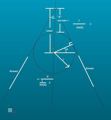
As long as two tangent faces can be measured/determined, all that is required to infer a radius is 1 point. 1 point is taken on the mid line of the two faces to determine the excosec and a little bit of algebra later you have a radius.
$$ NO,
[B]     ASSUMPTION: BOTH FACES ARE CO-TANGENT TO RADIUS[/B]
[B]     edit: i suppose the second assumption would be "the radius has perfect form"[/B]
$$ NO,
[B]     Two line measurements are taken.
            One on either tangent of the corner radius with
            vectors pointing towards the radius being measured.
            The vector nominals in the command block screw with
            the construction of LIN3, otherwise the code as is would not
            matter what orientation it is in.
            (wont be a problem in real program)
            Could probably fix with expressions in vectors
            Manual mode for demonstration purposes only.[/B]

LIN1       =FEAT/LINE,CARTESIAN,UNBOUNDED
            THEO/<18.839,0,10>,<1,0,0>
            ACTL/<-119.063,-114.215,11.302>,<0.4934556,0.869771,0>
            MEAS/LINE,2,ZPLUS
              HIT/BASIC,NORMAL,<18.839,0,10>,<0,1,0>,<-119.063,-114.215,11.337>,USE THEO=YES
              HIT/BASIC,NORMAL,<108.2,0,10>,<0,1,0>,<5.926,106.092,11.266>,USE THEO=YES
            ENDMEAS/
LIN2       =FEAT/LINE,CARTESIAN,UNBOUNDED
            THEO/<100,-103.413,10>,<0,1,0>
            ACTL/<121.972,-136.12,11.265>,<-0.4351452,0.9003603,0>
            MEAS/LINE,2,ZPLUS
              HIT/BASIC,NORMAL,<100,-103.413,10>,<1,0,0>,<121.972,-136.12,11.265>,USE THEO=YES
              HIT/BASIC,NORMAL,<100,-23.975,10>,<1,0,0>,<17.756,79.513,11.265>,USE THEO=YES
            ENDMEAS/
            MODE/DCC
$$ NO,
[B]     Construct the point of intersection[/B]

PNT1       =FEAT/POINT,CARTESIAN,NO
            THEO/<100,0,10>,<1,0,0>
            ACTL/<5.377,105.125,11.284>,<0.4934556,0.869771,0>
[B]        CONSTR/POINT,INT,LIN1,LIN2[/B]
$$ NO,
[B]     Construct a mid line to use for vectors on pnt2.[/B]

LIN3       =FEAT/LINE,CARTESIAN,UNBOUNDED,NO
            THEO/<54.527,-45.473,10>,<0.7071068,0.7071068,0>
            ACTL/<-2.198,-124.836,11.284>,<0.0329234,0.9994579,0>
[B]        CONSTR/LINE,MID,LIN1,LIN2[/B]
$$ NO,

[B]     This constructed line isnt necessary and could be removed.
            A replacement could be the use of ANGLEBETWEEN()
            but the result would need converted back into vectors.
            Dont care enough to do that atm.
            Something with UNIT() maybe. note to self, wtf is CROSS(,)[/B]

            CHECK/100,1
            TOUCHSPEED/ 20
            PREHIT/2
$$ NO,
[B]     Flip pnt2 vector expresions to negative and add a large
            complimentary PREHIT distance if you would like this
            to measure inside rads
            ... pretty sure that should do it.[/B]

PNT2       =FEAT/POINT,CARTESIAN
            THEO/<120,0,10>,<[B]LIN3.I,LIN3.J,LIN3.K[/B]>
            ACTL/<3.513,48.49,11.281>,<0.0329234,0.9994579,0>
            MEAS/POINT,1,WORKPLANE
              HIT/BASIC,NORMAL,<[B]PNT1.X,PNT1.Y,PNT1.Z[/B]>,<[B]LIN3.I,LIN3.J,LIN3.K[/B]>,<3.513,48.49,11.281>,USE THEO=YES
            ENDMEAS/
            CHECK/0,1
DIM LOC1= POSITION OF POINT PNT2  UNITS=MM ,$
GRAPH=OFF  TEXT=OFF  MULT=10.00  OUTPUT=[B]NONE[/B]  FIT TO DATUMS=OFF  DEV PERPEN CENTERLINE=OFF  DISPLAY=DIAMETER
AX       MEAS    NOMINAL       +TOL       -TOL      BONUS        DEV     OUTTOL
X       3.513  [B]PNT1.X[/B]                                      -1.864
Y      48.490  [B]PNT1.Y[/B]                                     -56.635
TP    113.331        RFS  [B]80085[/B].000                 0.000    113.331      0.000 -------->
END OF DIMENSION LOC1
$$ NO,
[B]     LOC1 is only used to get the distance from the intersecting point
            to the measured point. However, loc1.tp.meas will always return
            the diametric true position even if you change the display to radius.
            Divide by 2[/B]

RAD1       =GENERIC/CIRCLE,DEPENDENT,CARTESIAN,OUT,$
            NOM/XYZ,<0+0,0+0,0+0>,$
            MEAS/XYZ,<[SIZE=16px][COLOR=#0000FF][B]PNT2.X+(-LIN3.I*RAD1.RADIUS)[/B][/COLOR][/SIZE],[SIZE=16px][COLOR=#0000FF][B]PNT2.Y+(-LIN3.J*RAD1.RADIUS)[/B][/COLOR][/SIZE],PNT2.Z>,$
            NOM/IJK,<0,0,1>,$
            MEAS/IJK,<0,0,1>,$
            RADIUS/0,[SIZE=16px][COLOR=#0000FF][B](LOC1.TP.MEAS/2)/((1/SIN(DEG2RAD(ANGLEBETWEEN(LIN1.IJK,LIN2.IJK))/2))-1)[/B][/COLOR][/SIZE]
$$ NO,
[B]     ^^The Bees Knees^^

            That Parenthesis Pasta is ugly but it still works.

            In the pursuit of visually displaying the radius in the correct position,
            I have accidently measured the center of the radius as well. No, I dont know
            why a feature referencing itself works.[/B]

DIM LOC2= LOCATION OF CIRCLE RAD1  UNITS=MM ,$
GRAPH=OFF  TEXT=OFF  MULT=10.00  OUTPUT=BOTH  HALF ANGLE=NO
AX       MEAS    NOMINAL       +TOL       -TOL        DEV     OUTTOL
R       49.163  RAD1.RADIUS  ****  ****      0.000      0.000 #--------
END OF DIMENSION LOC2
$$ NO,
[B]     was getting measurements under .001" deviation

            Id give her a +/- .002" accuracy.
            (as a complete guess, haven't done study yet)
            Should be most accurate at 90 degrees total angle
            with exponential increase in error at both limits.
            Smaller internal angle will be affected by line measurement acc.
            Larger internal angle will be affected by rad point measurement acc.
            Outside radius should be slightly more accurate for smaller -wait... no one cares[/B]


