
I recently had a part with a whole bunch of linear dimensions to/from edges where two parallel surfaces transition in height. Below is a picture as I’m sure that explanation didn’t make any sense. The linear dimension I am discussing measuring is in red.
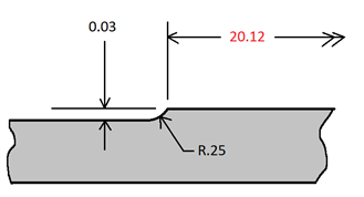
In some cases that 0.03in step height was only 0.010in on the print. In other cases it was more like .30in. Luckily, I had a nice big tolerance of +/-.030in to work with, so I didn’t need the utmost precision in finding that edge. Also, if the measurements I got with the CMM were reported near the edge of the tolerance or out even of tolerance, I had the option to verify them with hand measuring tools.
All I have at my disposal is a CMM with an analog scanning touch probe. I bet it would be much more accurate to pick up that edge with some sort of vision system, but I don’t have that. So, I had to be a bit creative finding those edges.
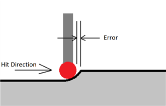
The first option was to use an auto edge point. But in this case the edge is just too small and not square. In many cases my probe radius was larger than the step height. Also, auto edge points really only work well on square edges, anything that is not square will have a bit of cosine error even if the depth is set to zero.
I have also heard of an old trick where you turn off probe radius compensation and take a hit on the edge at a define depth and trig out the position of the edge.
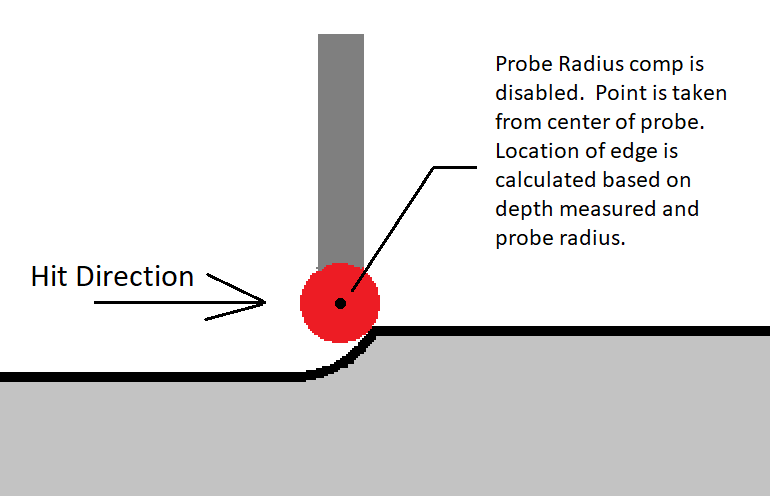
Frankly, I totally forgot about that trick until I started typing this up. If anyone has any experience doing it this way, please let me know how it has worked for you. Also, I’m curious if it works as well with an analog probe VS an old touch trigger probe. I suspect it doesn’t work as reliably with the analog probe as it would try to compensate the hit vector based on what it senses instead of just doing what it is told.
Another way to pick up that edge is to measure the arc with a circle, measure a line on the surface, then find the pierce point between that arc and the line. That works quite well if you have a good size arc, and I did that where I could, but in many cases on this part the arcs were just too small - just a few degrees. I couldn’t be confident that all the hits would actually hit the arc since the location has such a large tolerance.
Finally, the last option I could think of was to scan along these edges and find where the points start to transition over that edge. Using a scan point density of 40pts/mm would make 1 point every 0.001in - as much precision as a caliper, plenty for my needs.
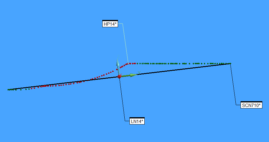
Well, I tried it out and was very pleased with the results. I verified in several places with manual measuring tools and replicated the measurements within 0.002in. In the Picture below HP14 is the point that was derived as the edge from the scan. You can see that it was able to discern the edge of a very mild transition.
Here is how I did it.
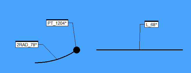
1) Measure a short linear open scan perpendicular to the edge to be found. The shorter the scan the easier it will be to find the edge, as will become a bit clearer in later steps.
2) Create a 3D line between the start point and the end point of that scan.
3) Create an alignment that is leveled to that line and rotated to a plane that is parallel to the surface that the edge is on. In my case DATUM_A which is a plane. Notice in the picture that the trihedran is tilted along LN14.
4) Use the MAXINDEX function to find which point of the scan is highest within that alignment. The edge will have the highest position value assuming that the edge is nice and sharp and there are no burrs or debris getting in the way.
5) Create a generic point from that scan point to represent the edge in question. Point HP14 in the picture below.
6) Return to the alignment that was being used prior
$$ NO,


LN14 =FEAT/LINE,CARTESIAN,UNBOUNDED,NO
THEO/<-9.9135,98.0705,-1.19>,<-0.0007492,-0.9931525,-0.1168224>
ACTL/<-9.9135,98.0705,-1.19>,<-0.0007491,-0.9931263,-0.1170454>
CONSTR/LINE,BF,3D,SCN710.HIT[1..1],SCN710.HIT[SCN710.NUMHITS],,
OUTLIER_REMOVAL/OFF,3
FILTER/OFF,WAVELENGTH=0

PA14 =ALIGNMENT/START,RECALL:ALN_ABC2,LIST=YES
ALIGNMENT/LEVEL,YMINUS,LN14
ALIGNMENT/TRANS,ZAXIS,LN14
ALIGNMENT/TRANS,XAXIS,LN14
ALIGNMENT/TRANS,YAXIS,LN14
ALIGNMENT/ROTATE,ZMINUS,TO,DATUM_A,ABOUT,YPLUS
ALIGNMENT/END

ASSIGN/PV14=MAXINDEX(SCN710.HITS.Z)

HP14 =GENERIC/POINT,DEPENDENT,CARTESIAN,$
NOM/XYZ,<SCN710.HIT[PV14].TX,SCN710.HIT[PV14].TY,SCN710.HIT[PV14].TZ>,$
MEAS/XYZ,<SCN710.HIT[PV14].X,SCN710.HIT[PV14].Y,SCN710.HIT[PV14].Z>,$
NOM/IJK,<ZE,ZE,1>,$
MEAS/IJK,<ZE,ZE,1>

RECALL/ALIGNMENT,INTERNAL,ALN_ABC2