hexagon logo

Can't interpret GD&T callout

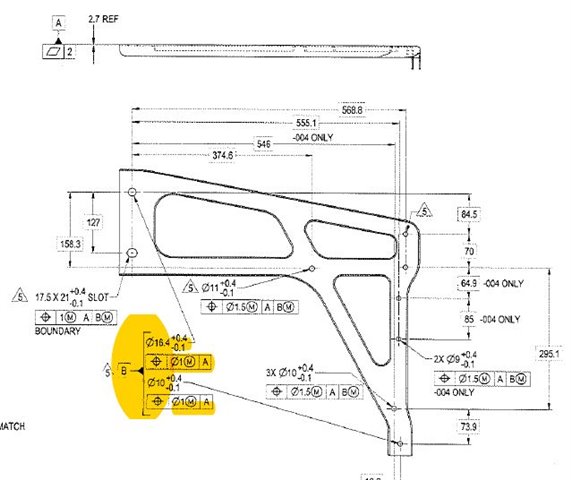
I have been doing GD&T for quite a few years and I am really stumped on what the intent of this call out is.  Was hoping someone could share some insight in what the intent is.  The are giving me 2 seperate holes to use as Datum B.  Typically, i would rotate to these, however, there is no Datum C.  That is fine, however they also have a max modifier on datum B in other FCF.  How can that be when each hole is a different size and i am only rotating datum B.  I think i am missing something here.

  • I think your interpretation is correct. It might have worked if there was no modifier in the other FCF.

  • In this day & age you have to take GD&T with a grain of salt because designers (especially recent engineering grads from fancy colleges) who use it tend to have little practical understanding  how it works in the real world.

    Here looks like they are concerned about drilling those holes perpendicularly to A. Datum modifier is there for datum shift nothing else. 

    I would use 1st B (upper left) as my xy origin point and 2nd B as datum C for clocking. Use trig to figure out the angle & compensate in the alignment window. 

    I never bother with datum shifts; the machinist doesn't care much either. 

    If you aren't sure about the datum scheme I would advise going to the designers & ask them for the assembly CAD or colored drawing so you yourself build the datum scheme per assembly precedence. Then go thru with them what their reasoning is for this GD&T or that GD&T. If that's futile go to the machinist/CAM programmer & inquire what is their order of operations. Then go to your boss & explain what you will do. That way it ain't on you. 

  • According to ASME Y 14.5, a datum is defined as 
    "datum: a theoretically exact point, axis, line, plane, or combination thereof derived from the theoretical datum feature simulator."

    So although it's not clear, B Datum in this instance is an implied line between the centroids of the two circles, with allowable feature size MMB bonus for each datum feature.

    It's sketchy as a datum, as the origin point is ambiguous... But if taken literally (with the line as ONE feature of size, (Note in the definition it's single tense, not plural)), the origin would be the MIDPOINT of that line.

    Is that the intent of the engineer? Unlikely.  I would follow  's suggestion that you use the top left hole as origin and rotate about the bottom right, then trig out the basic rotation offset angle between the two datum holes within that alignment structure.  This would square up your alignment to be orthogonal to the print, to get your basics to report appropriately. 

    --If I got any OOS without the B datum MMB shift allowed in all the other non-datumed holes, I would change that datum alignment to a bestfit alignment of the two datum holes, as the alignment.

  • When my buddy went through engineer school recently, he said they spent about 1/2 of one class period discussing GD&T.  Which makes sense based on some of the drawings new engineers come up with Laughing

  • Yeah ASU engineering undergrad program provides less than one week of curricula related to GD&T.  It's appalling.

  • In this day & age you have to take GD&T with a grain of salt because designers (especially recent engineering grads from fancy colleges) who use it tend to have little practical understanding  how it works in the real world.

    Tru dat...  

    I never bother with datum shifts; the machinist doesn't care much either. 

    I thought I was the only one.  Good Lord, I swear engineer types are just trying to pad their drawings by adding too many modifiers, incorrect Datums, or just plain wrong datums.