hexagon logo

Datum Reference Frame

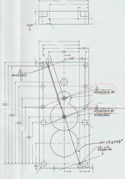
I don't have an image to post but the description is simple: I have a cuboid part (a block) with dimensions shown against XYZ that match the cuboid planes. The DRF, alternatively, is the top plane (+Z = Datum A), a hole on the top plane (Origin = Datum B) and another hole on the top plane (Rotation = Datum C). The holes are not aligned with the XYZ (Datum B is on one side of the top surface and Datum C on the other). The angle between them with respect to the XYZ of the cuboid dimensionals is nominally 17.6558 degrees.

So, to measure True Positions of other holes against A/B/C, the DRF is rotated that number of degrees in relation to the dimensions to the FCF of the holes to be checked.

Am I correct in surmising that I should rotate the X/Y dimensional components of the measured holes to be checked to match the angle between the rectilinear orthonormal CSY of the cuboid dimensions and the DRF CSY?

Sorry if this seems fundamental but every single example online is the most simple alignment of DRF with no such misalignment between the dimensional alignment and datum alignment.

Thanks!
Parents
  • Option 2 looks to be the most relevant. So, basically, do an Alignment (CSY) square to the drawing (already done so that I can get to the datums and features to be probed), create a new CSY from the Alignment rotated to the holes (CSY using B->C as Rotate - Datum B is already the Origin).

    Not sure about the offset rotation. In Quindos, if I use the CSY pointing along B->C (-X in this case), using the Basic dims (positive or negative) to the 2 holes gives me incorrect values. Not sure how to 'offset rotate' that without fundamentally transforming the CSY back to where it was in Alignment. I think that more explanation is required.

    I have scanned and 'edited' the drawing just to show the areas of interest and layout of the Datums. Note that the angled lines were drawn on by me just to see the relationship and how the rotation might affect the evaluations. The 2 TP FCF's are circled in red (by the engineer requesting the measurements). It also should have been noted that the angle stated is calculated from the X/Y dimensions between Datums B and C and is not a given dimension.

    Thank you so much for your input so far!!

Reply
  • Option 2 looks to be the most relevant. So, basically, do an Alignment (CSY) square to the drawing (already done so that I can get to the datums and features to be probed), create a new CSY from the Alignment rotated to the holes (CSY using B->C as Rotate - Datum B is already the Origin).

    Not sure about the offset rotation. In Quindos, if I use the CSY pointing along B->C (-X in this case), using the Basic dims (positive or negative) to the 2 holes gives me incorrect values. Not sure how to 'offset rotate' that without fundamentally transforming the CSY back to where it was in Alignment. I think that more explanation is required.

    I have scanned and 'edited' the drawing just to show the areas of interest and layout of the Datums. Note that the angled lines were drawn on by me just to see the relationship and how the rotation might affect the evaluations. The 2 TP FCF's are circled in red (by the engineer requesting the measurements). It also should have been noted that the angle stated is calculated from the X/Y dimensions between Datums B and C and is not a given dimension.

    Thank you so much for your input so far!!

Children
No Data