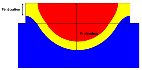
In my simulation using the WAAM (Wire Arc Additive Manufacturing) process with stainless steel as the material, I observed that the weld bead does not fully melt. I would like to understand the possible causes behind this issue

Your Products have been synced, click here to refresh
In my simulation using the WAAM (Wire Arc Additive Manufacturing) process with stainless steel as the material, I observed that the weld bead does not fully melt. I would like to understand the possible causes behind this issue

Hi Kamar,
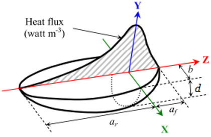
I assume u did use a conventional heat source geometry (Goldak double ellipsoid source model). With this heat source geometry you have to make sure that it will overlap the deposit, as the heat flux is distributed with a Gaussian function. So the border area gets a really small part of the heat flux and don't melt at all.

You can use this rule fo thumb from arc welding as a starting point for the heat source calibration:

Please check your peak temperature too.
Best regards,
Julian
hi
Thank you for your response. The formulas you provided appear to be related to fillet welding. Do they also apply in the case of a rectangular bead deposited on a flat plate? More specifically, what would be the appropriate value of the parameter "a" in this case?
kamar
hi
Thank you for your response. The formulas you provided appear to be related to fillet welding. Do they also apply in the case of a rectangular bead deposited on a flat plate? More specifically, what would be the appropriate value of the parameter "a" in this case?
kamar
The posted rule of thumb indeed does apply for fillet welding and not really for DED. "a" is usually the throat thickness.
Basically you can have a quite big heat source because no energy will be lost as the heat flux will be distributed between all integration points captured by the heat source.
The size of the heat source strongly depends on the process. If it's just a single wall, the heat source can be quite wide. If there are multiple tracks next to each other, you have to be quite careful with the width. Is the heat source to wide, you will input to much energy into the neighboring tracks.
I would start with something like:
b = 1/2 x "width of the layer" + 1/5 x "width of the layer"
d = "high of the layer" + 1/5 x "high of the layer"
af = b
ar = 2 x b
And the make a cross section in the model view and check the overlap. If it looks good, run a couple of increments with a thermal simulation only and check the temperature field. If the melt pool is to small, increase the width and perhaps the efficiency to keep the temperature up.
Thank you for your answer .
kamar.
| © 2025 Hexagon AB and/or its subsidiaries. | Privacy Policy | Cloud Services Agreement |