hexagon logo

Problem with laser metal deposition as multilayer simulation

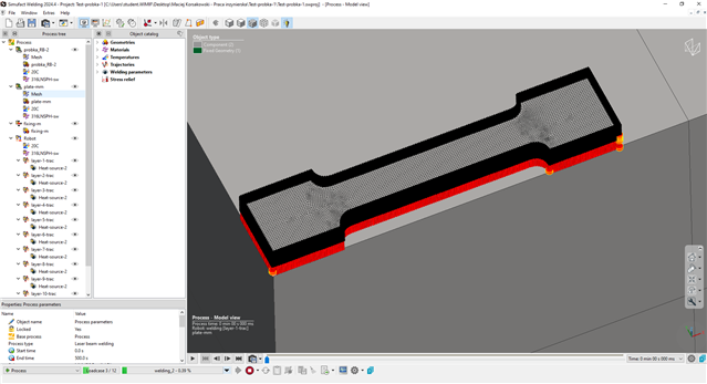
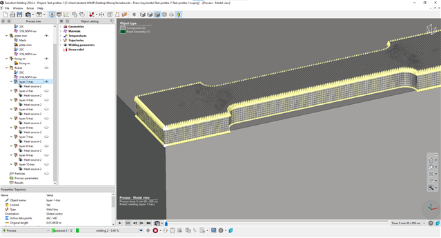
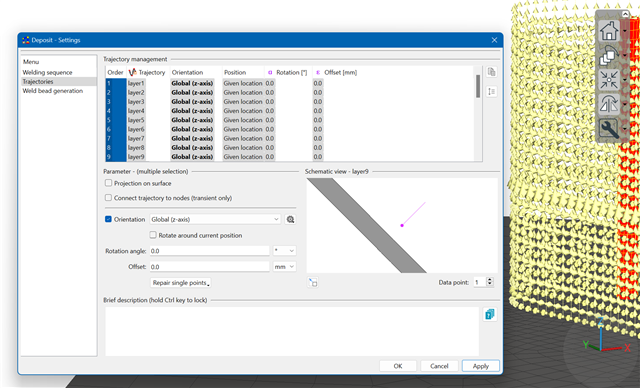
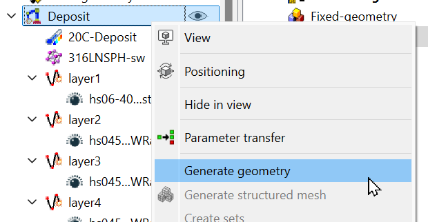
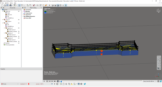
Hi, i have a problem with my multilayer simulation. I dont really know whats wrong because i am doing it for the first time with tutorial from hexagon to simulate my 3d model. For now i have problem with how to get fillers for each trajcetory (in tutorial they were made and we are just using them). Additionally i think my trajectories are done incorrectly and also like in fillers, we are just importing them so i don't know how to make them the right way. I am attaching some screenshots. If anyone could help me I would be very grateful.

  • Hi Maciej, 

    the first step is define your weld lines. You can import a GCode or a *.csv file for the trajetories or pick trajectories in your model. 

    Then you have to do the orientation. This can be done in the robot dialog or directly in the trajectory setting. 

    After that you can create a geometry around your weld lines: 

    Please enter the width of your tracks and the hight should be bigger as the real printing high (min ~1.5 times). Use a resolution around 1/3 of the high and activate the "cut result with components" option, otherwise you'll get a some penetrations between your deposit and the substrate. Please check the info-sheet for more details:

    This geometry is only a surface, so you have to generate a volume mesh to use it in the simulation:

    The mesh size strongly depends on your simulation goal. If you want to simulate a big part with the focus on distortion, I suggest to use 2-4 elements over the width and 1-2 over the hight of each layer. If you focus on stresses and small parts, I suggest to use at lease 8 element over the width and 4 in hight direction:

    Then define and assign your heat source. I suggest to do the heat source slightly bigger as your tracks (width and depth).

    The last step would be "create sets". With this Simufact Welding will assign the elements to each trajectory based on the heat source size. 

    If you know click on a trajectory, the view will visualize which element are assigned:

    If you are not sure what to do, you can always check the info sheets. They will explain what is required in the dialog.

  • A quick remark: you just have the outline of your part covered by a trajectory. So basically you'll just print the outline of your part.  

  • Infosheets are really helpful, but I think I have a problem with my environment or licenses, because I don't have the same options as you. I don't have access to features like sets, generate geometry, structured mesh, or to generate trajectories. If I'm right, I also don't have the license for the additive module, so that might be the issue. I'm not sure if I can run this simulation properly without these options, and I don't know how to fix it. Additionally, this simulation is part of my engineering thesis defense, so it's really important for me to get it done the right way. I would really appreciate your help with this.

  • Yes, you didn't select direct energy deposition as your process type:


    Simufact Additive is a different simulation tool. The license you needed is Simufact Welding Direct Energy Deposition Solver: 

  • Okey, thank you very much. Now the previous problem is solved. I made everything with your instructions but when i'm starting simulation an error occurs with number 1009 and i found this in output logs:

    Error encountered in stress recovery. The output will reveal
                 which element has a particular problem. The error is usually
                 due to excessive deformation in the element. Note that this
                 can occur during the iterative process, so that it is not
                 always possible to visualize the excessive deformation.
                 Check the material behavior and the magnitude of the
                 incremental loads.
                 
                 Suggestion :
                 ------------
                 Activate the cut-back feature if using the AUTO LOAD, AUTO
                 STEP or AUTO INCREMENT solution schemes. This will allow the
                 analysis to automatically cut down the time step and to try
                 again from the end of the last converged increment. For the
                 AUTO LOAD procedure, the increment numbers are maintained as
                 specified in the input.
                 

    I don't really know what to do now or what I did wrong. I'm not sure if it matters, but I created the trajectories using Ultimaker Cura and imported them into Simufact using a G-code file. If this is not the correct method, how should I create the trajectories for each layer? I'm sorry if I'm being annoying — I've only been learning this for about a month, and it's quite difficult for me.

  • Regarding the exit 1005: Please check the dimension of your plate. It looks like as the plate is to big or at least the elements are to big compared with the elements of your part. The ratio of 1:4 should be the maximum for the difference in element size, otherwise you'll get a lot of problems during the calculation. 

    I suggest to calibrate the heat source first in a thermal simulation. This ensures that your problems aren't caused by to high temperatures. Here are some old slides you can use to calibrate your heat source.

    PDF

    I also suggest to check this presentation. This will give you a basic understanding.

    https://simcompanion.hexagon.com/customers/s/article/Simufact-Welding-speed-up-Guide-line-welding

    It looks like as you've quite a lot elements in your small part and very long trajectories. I suggest to use less element for your part (you'll need 96 GB of RAM for ~1 Mio elements) otherwise the simulation will run weeks. I also suggest to use the ATC (advanced thermal cycle). 

    Usually users start with a training to get the basics of modeling, post processing and debugging.