hexagon logo

Bushings as Bolts - Preload Strategies....

ADAMS/View 2022.4
 
I’m building a new model where I need to bolt two flex bodies together. Part of the goal of the model is to understand the changes in Bolt loads as the system is exercised. We are a “weld the heck out of stuff” kinda place, so please forgive the basic questions…
 
My initial thought was to apply Bushings as the Bolts and use the preload field to set the clamp load. Nice and linear, and a single modeling element handling everything. I also added a flex-flex contact between the mating surfaces. In my mind’s eye, this was the Bolt behavior I was setting up…
 
image
 
What happens looks more like this…
 
image
 
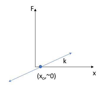
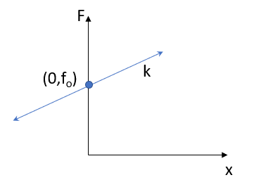
Looking in the help, this makes sense, since (in one direction, ignoring damping for now)…
 
Fx=-k*x+fo
 
I make a static-dynamic run, and the ppt shows the Bushing force as being near zero, as well as a small amount of Bushing (xo) deflection. I understand why this is happening, but I would like to see my preload and then the changes to it as the system is loaded.
 
So, I’ve heard of people “tuning” a Bushing in this type of model. What exactly does that mean? Here are the things I’m trying to get my desired (I think it’s what I want) behavior…
 
1.      Bolt/Bushing stiffness –
a.      Plain old k=AE/L
b.      Looking at Shigley to possibly modify this.
2.      Mating surface stiffness/contact –
a.      This “reaction” force is very low. No where near my total Bolt preload. 
b.      From a Free Body standpoint, I think I should be able to chase the Bolt loads through this interface, yes?
c.      Also looking in Shigley for suggestions.
3.      Adding a second modeling element to provide the preload only.
a.      The total of the “preload” Bushing/SFO and the “stiffness” Bushing would be the total force.
b.      Not crazy about doubling everything up, as the final model will have several flex bodies bolted on.
 
Interested in comments and criticism…
  • I think what you are seeing is the deflection in the contact reduces the preload!
    (First, your plots shows F=kx+F0, not F=-kx+F0)
    But you build the busing and applies the preload at model input condition. Contact penetration here is zero.
    You have some preload, let's say F0 = 10,000 N, and a stiffness of the 'bolt' of k=EA/L = 210000*48/50 ~ 2e5 N/mm
    To completely unload the bushing, the busing needs to contract L = F0/k = 1e4/2e5 = 0.05 mm That is not very much.
    Now your two plates start moving together and exert a contact force pushing them apart. Fc = kc*q^e is the static force.
    At what deflection q will Fc = F0 ? I.e. when is the forces in equilibrium with each other?
    There you will have your equilibrium/static position.
    The contact is pushed together a little bit and the bushing/bolt is extended a little bit. This is what you see in the results plotting.
     
  • Hi Jesper,
     
    Thanks for the reply.
     
    Yes, I think we're on the same page. To find equilibrium, a minimum energy state (yes?), there is some interference required by the mating surface contact and a little "k*x" from the bushing. (BTW, cranking up the mating surface contact stiffness makes for a very "chattery" model...Confused)
     
    My question is still the same. Is this how you, or anybody else, is doing this? Treat the bushing response as the change from the preload? Something else?
  • Yes, I've done this in the past.
    The 'tuning' is really the iterations required to change preload so that the correct preload is achieved after the static equilibrium. You can of course calculate it using contact stiffness and exponent on one side and bushing stiffness and preload on the other.