hexagon logo

Dear all, I tried to do modal analysis by creating beam elements with beam cross-sectional properties. However, when the modal analysis is done I get only bending modes not the torsional modes. How could I get the torsional modes? Thanks in advance.

Dear all,
I tried to do modal analysis by creating beam elements with beam cross-sectional properties. However, when the modal analysis is done I get only bending modes not the torsional modes. How could I get the torsional modes?
Thanks in advance.
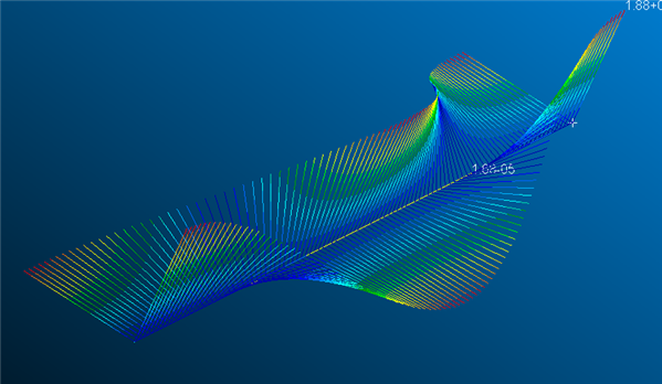
  • Hi, This sounds like it might be a problem of results visualization. I would suggest you make a very simple test of nominally straight beam using your section properties and enough elements to capture the modes you hope to see. visualising the torsion results within the calculated modes shapes is difficult. As this is a test model you could create two lines of nodes offset from your actual nodes in perpendicular direction to the beam ( so if the beam runs in X direction, the nodes would be offset in the Y and the Z) couple the nodes with RBE2 to the relevant beam nodes. These nodes will move (displacement) when the beam rotates and so you have something that you can visualise better in a post processor. If you use Patran, to see these nodes movement add some additional bar elements(purely for post processing) on the mpcs so they will be included in the deformation plot. You can then get something like this.
    image
    This illustrates the rotation mode in the overall mode. Without the extra nodes/elements the shape is dominated by the bending (you just have a line that is bent). For arbitrary cross-section shapes it is highly likely that your shear centre and neutral axis will not coincide and so any bending gives rotation and any rotation causes bending, i.e. there is not a unique bending or rotation only mode as they are coupled together.
  • Hello Arthur,
    First of all I would like to thank you for your response. As you said, in the first sight I thought that the reason which I do not see the torsional mode must be related to a visualization issue. However, when I check .f06 file I saw that the torsional mode does not exist. In order to check that if the torsional mode is really not calculated or not I prepared a simple beam element with a rectangular cross section and a real solid rectangular beam meshed with solid elements. When the analyses are completed I saw that beam elements did not calculate torsional modes really. In order you to see the results for yourself I am sharing the files with you. (Since I am not an expert on MSC Software Family, I might be sharing unnecessary files as well. Sorry for inconvenience, if there is any.)

    Attached Files (1)
  • Hi,
     
    the reason is that you are using CBAR elements with default settings. This is rather a historical thing but Nastran tends to keep historical default values so that something that was appropriate 20years ago as the default, maybe due to compute power and the need to simplify as much as possible for speed reasons, is still the default.
    If you look at the Linear Static user guide on CBAR elements:
    you will observe the note:
    The torsional mass moment of inertia is included in the BAR mass matrix by using NASTRAN BARMASS (398)=1. Note, by default, this term will not be included. For both values of PARAM COUPMASS, this term is added. 
     
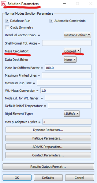
    Instead of editing the input deck ( or adding in an include card with the entry NASTRAN BARMASS=1 ) in the Patran Analysis setup Solution type/ Solution parameters you can turn on coupmass with the coupled mass entry:
    image
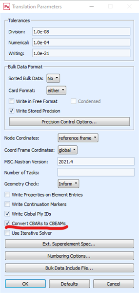
    alternatively in the Translation Parameters you can request conversion of all CBARS to CBEAMS. CBEAMS are more generic and do not have the compromises of simpler 1d beam types, computationally more expensive but that is not a real problem these days.
    image
     
     
  • Hi,
    Thank you very much for your precious time and advice. I get more than I seek. Your support is more than appreciated. Thank you again.
     
    Best wishes.