hexagon logo

Dear all, I tried to do modal analysis by creating beam elements with beam cross-sectional properties. However, when the modal analysis is done I get only bending modes not the torsional modes. How could I get the torsional modes? Thanks in advance.

Dear all,
I tried to do modal analysis by creating beam elements with beam cross-sectional properties. However, when the modal analysis is done I get only bending modes not the torsional modes. How could I get the torsional modes?
Thanks in advance.
Parents
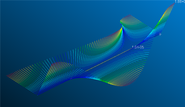
  • Hi, This sounds like it might be a problem of results visualization. I would suggest you make a very simple test of nominally straight beam using your section properties and enough elements to capture the modes you hope to see. visualising the torsion results within the calculated modes shapes is difficult. As this is a test model you could create two lines of nodes offset from your actual nodes in perpendicular direction to the beam ( so if the beam runs in X direction, the nodes would be offset in the Y and the Z) couple the nodes with RBE2 to the relevant beam nodes. These nodes will move (displacement) when the beam rotates and so you have something that you can visualise better in a post processor. If you use Patran, to see these nodes movement add some additional bar elements(purely for post processing) on the mpcs so they will be included in the deformation plot. You can then get something like this.
    image
    This illustrates the rotation mode in the overall mode. Without the extra nodes/elements the shape is dominated by the bending (you just have a line that is bent). For arbitrary cross-section shapes it is highly likely that your shear centre and neutral axis will not coincide and so any bending gives rotation and any rotation causes bending, i.e. there is not a unique bending or rotation only mode as they are coupled together.
Reply
  • Hi, This sounds like it might be a problem of results visualization. I would suggest you make a very simple test of nominally straight beam using your section properties and enough elements to capture the modes you hope to see. visualising the torsion results within the calculated modes shapes is difficult. As this is a test model you could create two lines of nodes offset from your actual nodes in perpendicular direction to the beam ( so if the beam runs in X direction, the nodes would be offset in the Y and the Z) couple the nodes with RBE2 to the relevant beam nodes. These nodes will move (displacement) when the beam rotates and so you have something that you can visualise better in a post processor. If you use Patran, to see these nodes movement add some additional bar elements(purely for post processing) on the mpcs so they will be included in the deformation plot. You can then get something like this.
    image
    This illustrates the rotation mode in the overall mode. Without the extra nodes/elements the shape is dominated by the bending (you just have a line that is bent). For arbitrary cross-section shapes it is highly likely that your shear centre and neutral axis will not coincide and so any bending gives rotation and any rotation causes bending, i.e. there is not a unique bending or rotation only mode as they are coupled together.
Children
No Data