hexagon logo

Creating Nominal Center Points of Constructed Scan Segment Arcs

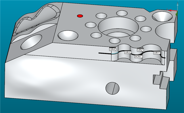
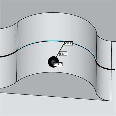
I'm trying to measure a bunch of radii from scanned data. They have all varying arc lengths. Some much less that the suggested 90°. So, I was going to create offset points from the nominal center of all the constructed arcs. Then use the nominal center points and a point from the arc (ex: CIR1.HIT[CIR1.NUMHITS/2]) and create a best fit line then measure the length of the line to get the size of the radius. I've got approximate 350 constructed circles from scan segment. So I'm trying to write a code to construct the points and the lines. For the record, I have no idea what I'm doing. I've just cobbled together a few things I've seen on here. I get the code to run without error but nothing happens. No features get created. What am I doing wrong? 

Sub Main()

Dim PCDApp As Object
Dim PCDPartPrograms As Object
Dim PCDPartProgram As Object
Dim PCDCommands As Object
Dim PCDCommand As Object
Dim cmd As Object

Set PCDApp = CreateObject("PCDLRN.Application")
Set PCDPartPrograms = PCDApp.PartPrograms
Set PCDPartProgram = PCDApp.ActivePartProgram
Set PCDCommands = PCDPartProgram.Commands

Dim NumFeat As Integer
Dim NumSelect As Integer
Dim I As Integer
Dim MidHit As Integer

Dim nX as Double
Dim nY as Double
Dim nZ as Double

Dim CircName As String
Dim CenterPtName As String
Dim RadLineName As String

Dim CircCenter
Dim PCDFeatCmd

NumFeat = 0
NumSelect = 0
' Enumerate commands
For Each PCDCommand In PCDCommands
' Constructed feature
  If PCDCommand.IsConstructedFeature And PCDCommand.Feature = CONST_SCAN_SEG_ARC Then 
    CircName(NumFeat) = PCDCommand.ID
    CenterPtName = CircName & "_CENTER"
    RadLineName = CircName & "_RADLINE"
    Set PCDFeatCmd = PCDCommand.FeatureCommand
    Set CircCenter = PCDFeatCmd.GetPoint(FPOINT_CENTROID, FDATA_THEO, CircName)
    nX = CDbl(CircCenter.X)
    nY = CDbl(CircCenter.Y)
    nZ = CDbl(CircCenter.Z)
    MidHit = PCDCommand.GetText(N_HITS, 0) / 2
    'CREATE OFFSET CENTERPOINT
    Set cmd = PCDCommands.Add(511, True)
    retval = cmd.PutText (nX, F_OFFSET, 1)
    retval = cmd.PutText (nY, F_OFFSET, 2)
    retval = cmd.PutText (nZ, F_OFFSET, 3)
    retval = PCDCommand.PutText (CenterPtName, ID, 0)
    retval = PCDCommand.SetToggleString ("ORIGIN", REF_ID, 0)
    retval = PCDCommand.SetToggleString (1, COORD_TYPE, 0)
    'CREATE BF RADIUS LINE
    Set cmd = PCDCommands.Add(541, True)
    retval = PCDCommand.PutText (CenterPtName, REF_ID, 1)
    retval = PCDCommand.PutText (CircName & ".HIT[" & MidHit & ".." & MidHit & "]", REF_ID, 2)
    retval = PCDCommand.PutText (RadLineName, ID, 0)
    If (NumFeat < 1000) Then
      NumFeat = NumFeat + 1
    End If
  End If
Next PCDCommand

PCDPartProgram.RefreshPart

'***** Cleanup
Set PCDCommand = Nothing
Set PCDCommands = Nothing
Set PCDPartProgram = Nothing
Set PCDPartPrograms = Nothing
Set PCDApp = Nothing
'*****


End Sub


typo
[edited by: Cliff Stearns at 5:01 PM (GMT -5) on May 9, 2025]
Parents
  • Did you mark the script command in your program? Otherwise it won't execute.

    This seems a little suspect:
    retval = PCDCommand.PutText (CircName & ".HIT[" & MidHit & ".." & MidHit & "]", REF_ID, 2)

    This creates something like CIR1.HIT[1..1], if it is a line it should probably say CIR1.HIT[1]:
    retval = PCDCommand.PutText (CircName & ".HIT[" & MidHit & "]", REF_ID, 2)

  • I didn't put a script command in my program. I just ran it from basic script editor. Do I have to insert a script command in my program?

    I did the hit like that because I made a sample program to export in basic so I could see the names of things. When I was constructing the line in my sample program it kept giving me an invalid index error when I changed CIR1.HIT[42..42] to CIR1.HIT[42].

  • When I run the script, I get no errors, but nothing happens. No points created. No lines created. The screen refreshes, that's it.

  • I'll take a look. I unfortunately have never constructed a Scan Segment Arc. How do I do that? I'm going to make a test script on my end.
    -- Never mind, I figured it out. I'll test real quick.

    So I need cast a point to the centroid of this circle from the scan segment, and a line to the middle point of the circle constructed? I just thought, if your N_HITS is an odd number, dividing by 2 would not work as you'd get 4.5 if you had 9 hits. Are they all even?

  • SCN1       =FEAT/SCAN,LINEAROPEN,NUMBER OF HITS=243,SHOW HITS=NO,SHOWALLPARAMS=NO
                MEAS/SCAN
                  BASICSCAN/LINE,NUMBER OF HITS=243,SHOW HITS=NO,SHOWALLPARAMS=NO
                  ENDSCAN
                ENDMEAS/
    CIR1       =FEAT/CIRCLE,CARTESIAN,IN,NO
                THEO/<0.4724,2.3228,-0.2203>,<0,0,1>,0.5906
                ACTL/<0.4724,2.3228,-0.2203>,<0,0,1>,0.5906
                CONSTR/CIRCLE,SCAN_SEGMENT,BF,SCN1,0.184302,2.2583087,-0.2203124,0.7334256,2.1847235,-0.2203125,0,0,0
    CIR2       =FEAT/CIRCLE,CARTESIAN,OUT,NO
                THEO/<0.9213,2.126,-0.2203>,<0,0,1>,0.3898
                ACTL/<0.9213,2.126,-0.2203>,<0,0,1>,0.3898
                CONSTR/CIRCLE,SCAN_SEGMENT,BF,SCN1,0.7460906,2.2113933,-0.2203125,1.0909108,2.2218878,-0.2203125,0,0,0
    CIR3       =FEAT/CIRCLE,CARTESIAN,IN,NO
                THEO/<1.2598,2.3228,-0.2203>,<0,0,1>,0.3937
                ACTL/<1.2598,2.3228,-0.2203>,<0,0,1>,0.3937
                CONSTR/CIRCLE,SCAN_SEGMENT,BF,SCN1,1.1017995,2.2054785,-0.2203125,1.4324647,2.2282214,-0.2203125,0,0,0
    CIR4       =FEAT/CIRCLE,CARTESIAN,OUT,NO
                THEO/<1.6207,2.1654,-0.2203>,<0,0,1>,0.3937
                ACTL/<1.6207,2.1654,-0.2203>,<0,0,1>,0.3937
                CONSTR/CIRCLE,SCAN_SEGMENT,BF,SCN1,1.441073,2.2459341,-0.2203125,1.611191,2.3619761,-0.2203125,0,0,0

    This is my sample program for testing purposes. I want to use the nominals from the center of the radii to create an offset point so the center point is always the nominal value, then construct a line from the offset point and a measured point on the radius. If there's a rounding function that wouldn't hurt. I figured since I defined it as an integer, it would round it for me but like I said. I have no idea what I'm doing haha

  • I want the script to essentially do this. I just added the assignment for clarity.

    CIR1       =FEAT/CIRCLE,CARTESIAN,IN,NO
                THEO/<0.4724,2.3228,-0.2203>,<0,0,1>,0.5906
                ACTL/<0.4724,2.3228,-0.2203>,<0,0,1>,0.5906
                CONSTR/CIRCLE,SCAN_SEGMENT,BF,SCN1,0.184302,2.2583087,-0.2203124,0.7334256,2.1847235,-0.2203125,0,0,0
                ASSIGN/V1=ROUND(CIR1.NUMHITS/2)
    PNT1       =FEAT/POINT,CARTESIAN,NO
                THEO/<0.4724,2.3228,-0.2203>,<0,0,1>
                ACTL/<0.4724,2.3228,-0.2203>,<0,0,1>
                CONSTR/POINT,OFFSET,ORIGIN,CIR1.TX,CIR1.TY,CIR1.TZ
    LIN1       =FEAT/LINE,CARTESIAN,UNBOUNDED,NO
                THEO/<0.4724,2.3228,-0.2203>,<-0.1493052,-0.9887912,0>
                ACTL/<0.4724,2.3228,-0.2203>,<-0.1493052,-0.9887912,0>
                CONSTR/LINE,BF,3D,PNT1,CIR1.HIT[V1..V1],,
                OUTLIER_REMOVAL/OFF,3
                FILTER/OFF,WAVELENGTH=0

  • When I try to do the CONSTR/POINT,OFFSET,ORIGIN,CIR1.TX,CIR1.TY,CIR1.TZ it is creating 2 points in a single point. At least visually on my CAD. Is that the same for you? I feel like doing a CAST point would do the same thing, just the vectors would not be perfect

  • I could go around my program and paste this with pattern after every scan segment arc but I wanted to learn how to do some cool script haha

    CIR1       =FEAT/CIRCLE,CARTESIAN,IN,NO
                THEO/<0.4724,2.3228,-0.2203>,<0,0,1>,0.5906
                ACTL/<0.4724,2.3228,-0.2203>,<0,0,1>,0.5906
                CONSTR/CIRCLE,SCAN_SEGMENT,BF,SCN1,0.184302,2.2583087,-0.2203124,0.7334256,2.1847235,-0.2203125,0,0,0
                ASSIGN/CIRCLE_ID=GETCOMMAND(527,"UP",1)
                ASSIGN/MIDHIT=ROUND(CIRCLE_ID.NUMHITS/2)
    PNT1       =FEAT/POINT,CARTESIAN,NO
                THEO/<0.4724,2.3228,-0.2203>,<0,0,1>
                ACTL/<0.4724,2.3228,-0.2203>,<0,0,1>
                CONSTR/POINT,OFFSET,ORIGIN,CIRCLE_ID.TX,CIRCLE_ID.TY,CIRCLE_ID.TZ
    LIN1       =FEAT/LINE,CARTESIAN,UNBOUNDED,NO
                THEO/<0.4724,2.3228,-0.2203>,<-0.1493052,-0.9887912,0>
                ACTL/<0.4724,2.3228,-0.2203>,<-0.1493052,-0.9887912,0>
                CONSTR/LINE,BF,3D,PNT1,CIRCLE_ID.HIT[MIDHIT..MIDHIT],,
                OUTLIER_REMOVAL/OFF,3
                FILTER/OFF,WAVELENGTH=0

  • PNT1 =FEAT/POINT,CARTESIAN,NO
    THEO/<0.4724,2.3228,-0.2203>,<0,0,1>
    ACTL/<0.4724,2.3228,-0.2203>,<0,0,1>
    CONSTR/POINT,OFFSET,ORIGIN,CIRCLE_ID.TX,CIRCLE_ID.TY,CIRCLE_ID.TZ

    Does this not create multiple points for you on the CAD? Or just 1?

  • The point of doing the offset point is to lock in the nominal value (could use a generic point too). Because on the actual part I'm checking most of my scanned radii are less than 90° of an arc. So this is my way of measuring a small arc circle without using a Fixed Radius circle, aligning to the center, and then measuring the polar radius. There are 350 ish radii on this thing so that would be very time consuming.

  • What should your nominal value be for these Radii? I was wondering if your method was getting you the correct nominal when going to reporting the length of the line

Reply Children
  • For the sample program it's this:

    DIM LOC1= LOCATION OF LINE LIN1  UNITS=IN ,$
    GRAPH=OFF  TEXT=OFF  MULT=10.00  OUTPUT=BOTH  HALF ANGLE=NO
    AX    NOMINAL       +TOL       -TOL       MEAS        DEV     OUTTOL
    L       0.2953     0.0100     0.0100     0.2953     0.0000     0.0000 ----#----
    END OF DIMENSION LOC1
    DIM LOC2= LOCATION OF CIRCLE CIR1  UNITS=IN ,$
    GRAPH=OFF  TEXT=OFF  MULT=10.00  OUTPUT=BOTH  HALF ANGLE=NO
    AX    NOMINAL       +TOL       -TOL       MEAS        DEV     OUTTOL
    R       0.2953     0.0100     0.0100     0.2953     0.0000     0.0000 ----#----
    END OF DIMENSION LOC2

    It's a weird number because it's 7.5mm and I'm in inches.

  • If you do a Distance Dimension instead, and then select PNT1, and CIR1, then select add or subtract radius option do you get the same nominal value?

  • Only difference is it's negative

    DIM DIST1= 2D DISTANCE FROM POINT PNT1 TO CIRCLE CIR1     (CENTER TO CENTER),SUB_RADIUS  UNITS=IN,$
    GRAPH=OFF  TEXT=OFF  MULT=10.00  OUTPUT=BOTH
    AX    NOMINAL       +TOL       -TOL       MEAS        DEV     OUTTOL
    M      -0.2953     0.0100     0.0100    -0.2953     0.0000     0.0000 ----#----

  • Pick Add Radius instead, it may be negative or positive depending on whether you select Add or Subtract. Which feature you select first, and possible which side of the part the circle feature is located. I think only Add or subtract may matter. This will save you from needing to construct lines all over your program if it works for you this way too. And your script would end up less involved, and wouldn't need your variable statements for N_HITS / 2. Don't worry, you can still do a cool script, just an easier one

  • That would be easier. It did change to positive when I selected "add radius" instead. I'm just not entirely sure that would give me the result I want. Especially the smaller arc-ed radii. If there's only 20° of an arc, the measured circle could be wacky which could make my results look crazy. I really wish they just dimensioned all these pockets as surface profile then I wouldn't have had any of these issues haha. I still am going to report them as profile as a secondary verification.

  • I apologize for pushing you so far off topic into another subject and method entirely from your original question.

    Let's get back to what you would like your script to do. Do you still want to continue using your lines method with Location dimensions for line length?

  • Yes the line method or create a cast point from a hit on the circle and then measure it back to the offset/generic point nominal center of the circle.

  • Sorry, I've been trying to get this to work for me properly so I can tell if it is working correctly if I help you with your script. Been a pain in the butt trying to get the scans to do what I want, but I got there. So have you tried executing your script at all since you posted, or changed anything yet?

  • I tried to put a message box inside the loop, and it will not pop up, so I think there's an issue with the loop.

  • I think I figured out why, it's a good thing I created this offset point myself. So the Offset point has a required Result = segment in the exported basic script.

    So you have to have the 3 Result = for each F_OFFSET segment and can't just use PutText, but need to use SetExpression

    You will also need to add Variable --> Dim Result As Long

        retval = DmisCommand.PutText ("PNT1", ID, 0)
        retval = DmisCommand.PutText ("ORIGIN", REF_ID, 0)
        retval = DmisCommand.SetToggleString (1, COORD_TYPE, 0)
        retval = DmisCommand.PutText ("-1.103", F_OFFSET, 1)
        retval = DmisCommand.PutText ("-0.6445", F_OFFSET, 2)
        retval = DmisCommand.PutText ("0.7911", F_OFFSET, 3)
        retval = DmisCommand.SetToggleString (1, USER_DEFINED_THEOS, 0)
      Result = DmisCommand.SetExpression("CIR1.TX", F_OFFSET, 1)
      Result = DmisCommand.SetExpression("CIR1.TY", F_OFFSET, 2)
      Result = DmisCommand.SetExpression("CIR1.TZ", F_OFFSET, 3)

    Where did you get this bit of code from? Trying to figure out what creates it

    Set CircCenter = PCDFeatCmd.GetPoint(FPOINT_CENTROID, FDATA_THEO, CircName)