hexagon logo

Report reading for enigneers

Today the engineers are bothering me asking me how they can know what direction on the part the hole is out of tolerance. Like shown in the attachment. They like focusing on the graphical depiction of the out of tolerance.

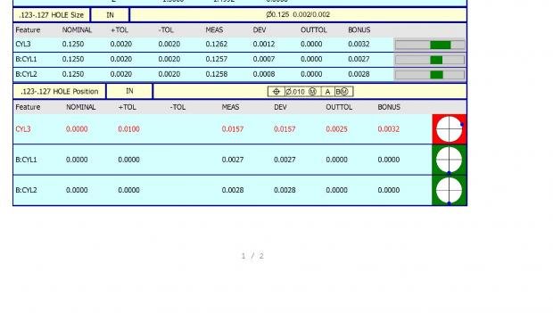
To be honest i'm not really sure how I can express to them how that shows what direction. I believe it is based on the alignment the part is dimensioned to. Is there some help file/guide I can point them (and myself) to? I can see there is an out of tolerance go into the program and zoom in on the feature and see in where it is compared to where it should be, but that doesn't help the engineers reading the report. Them being able to figure it out instead of coming to the lab and emailing me would be great. So any help or insight on this guys? Thanks in advance!
Parents
  • Thank you all for your answers so far. sealevel we aka I am still experimenting with what I should name things. We first tried ballooned drawings attached to the report using adobe, but the engineers didn't like that. So now i'm trying calling out holes as they are on drawings such as .250 4 hole pattern on datum A. So far no negative feedback on the names yet. I will point out the XYZ to them as well as work on playing with the report. Thanks again guys this forum is always a life saver.
Reply
  • Thank you all for your answers so far. sealevel we aka I am still experimenting with what I should name things. We first tried ballooned drawings attached to the report using adobe, but the engineers didn't like that. So now i'm trying calling out holes as they are on drawings such as .250 4 hole pattern on datum A. So far no negative feedback on the names yet. I will point out the XYZ to them as well as work on playing with the report. Thanks again guys this forum is always a life saver.
Children
No Data