hexagon logo

Custom Probe Builder Utility

I have scoured every thread on the forum about custom probes and how to build/save them. I recently purchased 1MM and 1.5MM x 21MM probes. My drop down list has, for the most part, tips in increments of 10mm. It seems possible that I can calibrate to, say, a 1x25mm and everything would seemingly fall in line, but I'd really like to set this up more properly.

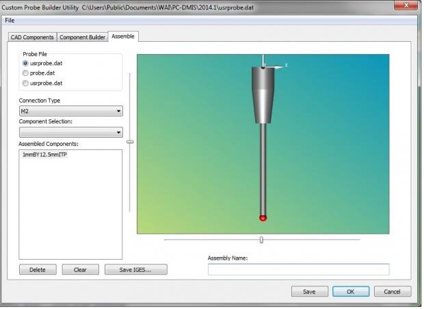
I had Hexagon build these probes after I gave it a shot, just to be sure I was doing it correctly. And I can pull up those files in the customer probe builder. After I see the IGES files for these probes, I don't really know how to go from there. Do I need to build everything from the "CAD Component" and "Component Builder" up? All I really want is the new tip itself to be in the drop down box, so I can add to the right connections?

Essentially - where do I go from the SS attached?
  • You have to go in and open the probe.dat file as a txt and build or add the probe like this example:

    ITEM:TIP1BY20.5MMtcSHANK M2
    begintip
    ribcount 10
    color 142 142 142
    cylinder 0 0 0 0 0 -2.5 3
    cone 0 0 -2.5 3 0 0 -5.7 1
    color 80 80 80
    cylinder 0 0 -5.7 0 0 -20.5 1
    sphere 0 0 -20.5 1
    hotspot 0 0 -20.5 0 0 1 1 14.15shank
    endtip


    Hexagon service is usually very helpful will help build the correct probe that you need.
  • ITEM:1mmBY12.5mmITP M2
    begintip
    color 128 128 128
    ribcount 20
    cylinder 0.000 0.000 0.000 0.000 0.000 -3.000 3.000
    cone 0 0 -3.000 3.000 0 0 -7.500 2.000
    cylinder 0.000 0.000 -7.500 0.000 0.000 -20.000 0.800
    color 255 0 0
    sphere 0 0 -20.000 1.000
    hotspot 0 0 -20.000 0 0 1 1.000 1.000 ball
    endtip

    ITEM:1.5mmBY12.5mmITP M2
    begintip
    color 128 128 128
    ribcount 20
    cylinder 0.000 0.000 0.000 0.000 0.000 -3.000 3.000
    cone 0 0 -3.000 3.000 0 0 -7.500 2.000
    cylinder 0.000 0.000 -7.500 0.000 0.000 -20.000 1.000
    color 255 0 0
    sphere 0 0 -20.000 1.500
    hotspot 0 0 -20.000 0 0 1 1.500 1.500 ball
    endtip

    Here are the two that Hexagon built for me under 1 .dat file. I think they were just misnamed by the technician.
  • I can not seem to get the Tips in my drop down box when building a new probe file under probe utilities. I can open them in wordpad from my C: Drive. They are available to pull up when opening the Custom Probe Builder. But I seem to be missing the step to actually get the tip in the drop down box to attach to connections to calibrate/measure, etc.
  • Try marking or selecting the probe.dat button:


    Also if I remember correctly (not 100% positive) you may have to close and reopen PC-DMIS after adding the new files to the probe.dat file
  • Try marking or selecting the probe.dat button:


    Also if I remember correctly (not 100% positive) you may have to close and reopen PC-DMIS after adding the new files to the probe.dat file


    Bingo!
  • possibly an irelivent question but are you sure you have the right tips selected? As I know for a fact that 1 and 1.5mm by 21mm exist in the directory as I use them but they are for M3 threads not M2.
  • Yep, I've always just done it by hand using text editor.

    I like this one:

    ITEM:HEAD-PH9-PH10T ARM
    color 0 0 0
    line -10 -30 0 -10 -30 -60 1
    line 10 -30 0 10 -30 -60 1
    line -30 -30 -20 30 -30 -20 1
    line -30 -30 -40 30 -30 -40 1
    line -30 -10 0 -30 -10 -60 1
    line -30 10 0 -30 10 -60 1
    line -30 -30 -20 -30 30 -20 1
    line -30 -30 -40 -30 30 -40 1
    line 30 -10 0 30 -10 -60 1
    line 30 10 0 30 10 -60 1
    line 30 -30 -20 30 30 -20 1
    line 30 -30 -40 30 30 -40 1
    line -10 30 0 -10 30 -60 1
    line 10 30 0 10 30 -60 1
    line -30 30 -20 30 30 -20 1
    line -30 30 -40 30 30 -40 1
    line -30 -10 0 30 -10 0 1
    line -30 10 0 30 10 0 1
    line -10 -30 0 -10 30 0 1
    line 10 -30 0 10 30 0 1
    line -30 -10 -60 30 -10 -60 1
    line -30 10 -60 30 10 -60 1
    line -10 -30 -60 -10 30 -60 1
    line 10 -30 -60 10 30 -60 1
    color 0 0 255
    face 4 -30 30 0 30 30 0 30 -30 0 -30 -30 0
    color 255 0 0
    face 4 30 30 0 30 30 -60 30 -30 -60 30 -30 0
    color 255 255 0
    face 4 -30 -30 0 30 -30 0 30 -30 -60 -30 -30 -60
    color 0 255 0
    face 4 -30 30 0 -30 -30 0 -30 -30 -60 -30 30 -60
    color 255 255 255
    face 4 30 30 -60 -30 30 -60 -30 -30 -60 30 -30 -60
    color 255 100 0
    face 4 -30 30 0 -30 30 -60 30 30 -60 30 30 0
    ring 0 -30 -30 0 1 0 20 4
    ribcount 10
    color 255 0 0
    cutsphere 0 -30 -30 0 1 0 8 0 -10000
    autojoint 0 0 -77 0 0 1 0 7.5 -180 180 b angle
    color 30 30 30
    ribcount 10
    cutsphere 0 0 0 0 0 1 50 18 -10000
    autojoint 0 0 0 -1 0 0 0 7.5 0 105 a angle
    color 142 142 142
    ribcount 10
    cylinder -22 0 0 -25 0 0 13
    connect -25 0 0 1 0 0 M8
  • Y'all who like the text editor are crazy. That is the worst UI in the history of 1s and 0s.