This is my current alignment:
Cylinder (Datum A counterbore) Z+ level
Cylinder (Datum A counterbore) X and Y origin
Plane (top of part) Z origin
I only have 5 of the 6 DOF constrained with rotation in Z free. First, I did a manual alignment based off the cylinder of the large counterbore (Datum A), and the top plane above the threads of the CAD model and then took those points with the jog box to align the physical part with my CAD model. Then I programmed the CMM to take 24 hits from Datum A and 8 hits from the top plane in DCC mode to form another alignment based on the more consistent DCC hits. Based on my understanding of my training materials, when all 6 DOF are not controlled, it is best to reference the startup alignment for the DCC alignment rather than build off the the manual alignment. This allows the machine to control the last degree of freedom that is not constrained in the alignment process.
I am having issues with measuring parallelism, locations of drilled holes, and the location of the notch in relation to the datum of the clevis. When I check the clevis mounted in one direction, my parallel measurements and hole and notch locations will be out of tolerance, but when I give the clevis a 180 degree rotation and clamp it back down in the fixture to recheck it, the measurements show up as being in tolerance.
My thoughts are that if I check the location of the notch between the ears of the clevis and find that it is shifted 0.022" off center positive in the y-axis, then it should be shifted 0.022" off center negative in the y-axis when I give the clevis a 180 degree rotation in the fixture. However, I will get a result saying it is shifted 0.005" off center negative in the y-axis, or even have it say the notch is now shifted only 0.002" positive in the y-axis. In either case, the notch location now shows up in tolerance. The location of the 0.500" and 0.250" holes drilled in the sides of the clevis ears also fluctuate on the x-axis. The locations measured in the z-axis remain consistent regardless of which way I mount the part to the fixture. The only other callout I do not have problems with are the perpendicularity of the 0.500" and 0.250" holes in relation to the cylinder of Datum A
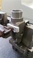
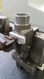
What would cause the parallelism of the machined clevis ears, in relation to Datum A, and the hole locations on the x-axis to be bad and then good when the part is rotated and rechecked? Am I messing up the alignment by not controlling all 6 DOF? Am I messing up my alignment reference by using the startup alignment? Or, could it be caused by the way our parts are being machined? We are currently having many problems holding these parts in our machines and preventing them from shifting. We don't even start with the Datum end when we reference the raw castings. We take an end mill cutter and cut the notch between the ears of the clevis, then we use that machined surface as the reference point in a 3-jaw chuck to bore, counterbore, and thread the datum end of the clevis, and finally we move them to a vise in a VMC to drill the side holes.
Thanks for any help.
Attached Files