hexagon logo

Alignment of Gear part

Daer all,

I am new guy for this user forum, currently I am using PC-DMIS in Camio 8.3. (Nikon Make)
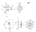
Recently, I found a problem with a alignment issue for my product. It is about a alignment of [A-B I C I D-E ] of part. Please refer to attached file for details. In that A & B are the circles through which we are going to construct a 3S line as a primary datum, then moving ahead C is plane as a secondary datum and lastly D & E are tooth width, from which we need to construct a line through theirs mid points. As in that I don't understand how to do alignment of this part ?
Because there are 2 lines and 1 plane. and mostly unluckily axis of 3D line and Plane is same. Its conflicts my alignment. CAMIO is not allowing to add 2 line 1 plane alignment anyway.

Any help would be greatly appreciated.


Thank you in advance. Slight smile

Best Regards,​​​​​​​
Atul N

Attached Files
  • Maybe...

    A-B as primary (level)
    D-E as secondary (rotation)

    A-B as X,Y origin
    C as Z origin

    Which would give you a [A-B | D-E | C ] alignment... yes, the order of the datums in the original DRF does not compute.
  • A-B - cylinder, locks two directions and two coordinates
    C - plane, can't lock direction as it's the same as A-B, locks the final coordinate
    D-E - line, locks the final direction (rotation)

    I don't see the problem?

    A1         =ALIGNMENT/START,RECALL:STARTUP,LIST=YES
                  ALIGNMENT/LEVEL,ZPLUS,CYL1
                  ALIGNMENT/TRANS,XAXIS,CYL1
                  ALIGNMENT/TRANS,YAXIS,CYL1
                  ALIGNMENT/TRANS,ZAXIS,PLN1
                  ALIGNMENT/ROTATE,XMINUS,TO,LIN1,ABOUT,ZPLUS
                ALIGNMENT/END
  • Thanks for your prompt reply.

    I agree on your thoughts. But It is fine if we origin C plane in Z...? Like it is not following 3-2-1 alignment structure(Plane-Line-Point) and also DRF?

    awaiting for your support.

    Thanks
  • Thanks @andersl for your prompt reply.

    As you said,
    If we lock C plane in Z axis without locking its direction, then how we supposed to lock its rotation after leveling?

    Also for D-E line, how it possible to follow 3-2-1 then?

    I am confused though.

    It would be great if you can suggest idea.

    Thanks
  • You can't create an alignment that is compatible with the primary, secondary and tertiary datums, because the DRF is wrong. Datum C and A-B is controlling the same rotation...

    A more "correct" DRF would be [A-B | D-E | C ] instead of [A-B | C | D-E ].
  • Well, as the datums lock as many degrees of freedom they can (that are not already locked), but no more, I don't see the problem (see my edit above), C is only locking the coordinate. Ninja said the same thing as answer to a duplicate post. There is no law that the datums should be in the order level, rotate, origin - here we have level and part origin, origin, rotate.

    Remember that the C plane should be measured/constructed as "tangent plane, perpendicular to A-B" (I.e. all we need is the Z coordinate of the "high point" of the plane).

    @ - it is not a good idea to post the same question in a lot of threads - people will waste their time answering something that has already been answered/discussed elsewhere.
  • I'm with Anders - I don't see a problem.


    I don't think it's technically correct in how it's drawn, but in this instance I think the intention is clear.

    I think what's maybe throwing you is it's attempting to show the combined datums (A-B and D-E) as datums in their own right - it's not necessary and just confusing (the A-B in the top left view makes sense, the A-B in the top right view is just wrong.)

    A-B is your primary - Level to this (3D line generated from A and B) and set two origins on in
    C sets the origin in the remaining direction
    Generate / Construct line D-E and rotate to that.

    I'm not clear from your post what software you're using? Is it Camio or PC-Dmis?


    Further to that, I think I understand what your issue is (and what VPT says) but if you follow the Can-May-Must way of thinking it's not a problem.


    If a datum CAN control a degree of freedom, and it MAY (i.e. that degree of freedom hasn't been controlled by a preceding datum) then it MUST.


    In the instance of Datum C, it MAY NOT control the leveling because it's been controlled by a previous datum, it CAN NOT control the rotation (because it's vector is co-linear with the primary datum). Hence it only controls what it can, which is an origin.
  • @ - Thank you. It does works.
    @ - Thanks for more clarification (for understanding my concern as well).
    I think it is working on (alignment discussed above like A-B for levelling, D-E for rotation and C for origining at Z).
    Below is the snap of same.
    I am working on CAMIO its version of PC-DMIS.


    - I apologise. I really did not have any intend to do ask repeated question. I joined this forum day before yesterday and I was not known this before. "it is not a good idea to post the same question in a lot of threads - people will waste their time answering something that has already been answered/discussed elsewhere."


    Thanks Ninja , andersl and VPT again.

    Have a great day !

    Attached Files
  • You can do it exactly as the drawing says, just remember that the C plane should be measured/constructed as "tangent plane, perpendicular to A-B" (I.e. all you need is the Z coordinate of the "high point" of the plane).
  • Thank you andersl.

    I will follow same.